4–320 869 MOTOR PROTECTION SYSTEM – INSTRUCTION MANUAL
CONTROL CHAPTER 4: SETPOINTS
Control
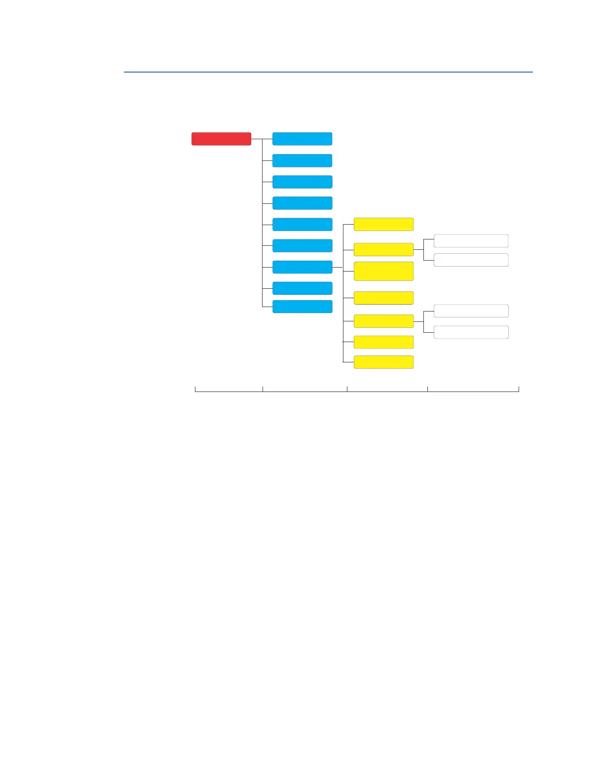
Figure 4-126: Control Display Hierarchy
Setpoint Group
The 869 relay provides six setpoint groups. All setpoints contained under the protection
setpoints are reproduced in six groups, identified as Setpoint Groups 1, 2, 3, 4, 5 and 6.
These multiple setpoints provide the capability for both automatic and manual switching
to protection settings for different operating situations. Automatic (adaptive) protection
setpoint adjustment is available to change settings when the power system configuration
is altered.
Automatic group selection can be initiated from the autoreclose, SETPOINT GROUPS and
by use of a
SET GROUP x ACTIVE setpoint input. The group selection can be initiated by this
input from any Flexlogic operands, inputs, pushbuttons or communications.
Group 1 is the default for the "Active Group" and is used unless another group is requested
t
o become active. The active group can be selected with the ACTIVE SETPOINT GROUP
setpoint, by SET ACTIVE x GROUP input or inputs from autoreclose, SETPOINT GROUPS. If
there is a conflict in the selection of the active group, between a setpoint, inputs and inputs
from functions, the higher numbered group is made active. For example, if the inputs for
Group 2, 4, and 6 are all asserted the relay uses Group 6. If the logic input for Group 4 then
becomes de-asserted, the relay uses Group 3. Under some application conditions, the user
requires that the relay does not change from the present active group. This prevention of a
setpoint group change can be applied by setting Change Inhibit inputs (1 to 16). If needed,
typically this change inhibit is done when any of the overcurrent (phase, neutral, ground,
sensitive ground, or negative sequence), overvoltage, bus or line undervoltage, or
underfrequency elements are picked-up.
Path:
Setpoints > Control > Setpoint Groups
Setpoints
Device
System
Inputs
Outputs
Protection
Monitoring
Control
FlexLogic
Motor Starting
Trip Bus
BF Initiate
BF Setup
Start Supervision
Level 1 Level 2 Level 3 Level 4
Breaker Failure
Switching Device
Control
VT Fuse Failure
Setpoint Group
Reduced VoltageStarting
Arc Flash
Testing

 Loading...


