CHAPTER 4: SETPOINTS MONITORING
869 MOTOR PROTECTION SYSTEM – INSTRUCTION MANUAL 4–279
Stator Inter-Turn Fault
When the insulation of the stator windings deteriorate, due to aging and other factors, this
creates an inter-turn fault. This type of fault is local and can happen either on the same
phase or different phases. This type of fault also causes heating at the local level but the
heat rapidly propagates causing the fault in other areas of the stator windings, as well. If
this fault can be detected just in time, the user can be warned ahead of major damage to
the system.
This element uses sequence components to det
ect stator turn failure of the induction
machine.
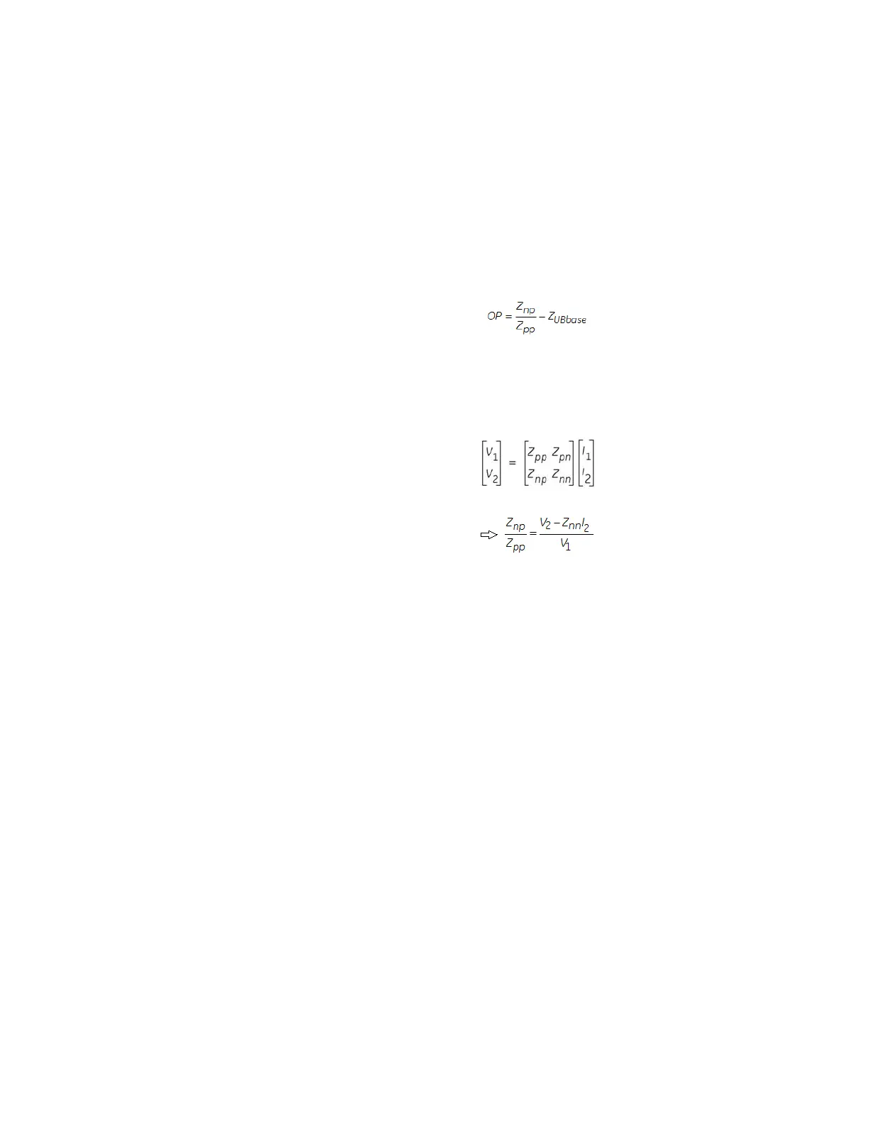
The operating condition can be defined as:
Where:
Z
pp
= positive sequence impedance
Z
np
= cross-coupled negative-to-positive sequence impedance
Z
UBbase
= learned unbalance base impedance
Z
np
/Z
pp
can be calculated from V1, V2, I2 and Z
nn
as:
Where:
V1 = positive sequence voltage calculated from the motor terminal voltages
V2 = negative sequence voltage calculated from the motor terminal voltages
I1 = positive sequence current calculated from the motor terminal currents
I2 = negative sequence current calculated from the motor terminal currents
Z
nn
= negative sequence impedance
For an ideal symmetrical machine Z
pn
= Z
np
= 0 i.e., decoupled positive and negative
sequence component circuit for the induction machine. However, in practice the situation
is not so and due to inherent asymmetry in the machine the Z
pn
and Z
np
values are small
non-zero quantities. When a turn fault occurs, the asymmetry in the system is further
aggravated which results in increase in this cross-coupling terms. The normalized cross-
coupled impedance, ratio of Z
np
to Z
pp
as defined by the above equation, is the key
operating signal that can effectively detect stator turn fault.
The inherent asymmetries in the machine at the time of commissioning and without stator
int
er-turn fault is represented as:
Z
UBbase
= (
Znp / Zpp) at 0 inter-turn fault
The setpoint Neg Seq Impedance (Z
nn
) required for the implementation of the above can be
set manually by the user if Neg Seq Imp Autoset is programmed as Manual. This value can
be calculated from the machine equivalent circuit parameters (i.e. winding inductance and
resistance). It can also be measured by deliberately applying the unbalance condition
during commissioning.
When Neg Seq Imp Autoset is set as Auto, the internal algorithm will calculate this value
fr
om the motor nameplate information (kWatts, rated voltage and number of poles) using
the Heuristic method.

 Loading...


