3–2 869 MOTOR PROTECTION SYSTEM – INSTRUCTION MANUAL
FRONT CONTROL PANEL INTERFACE CHAPTER 3: INTERFACES
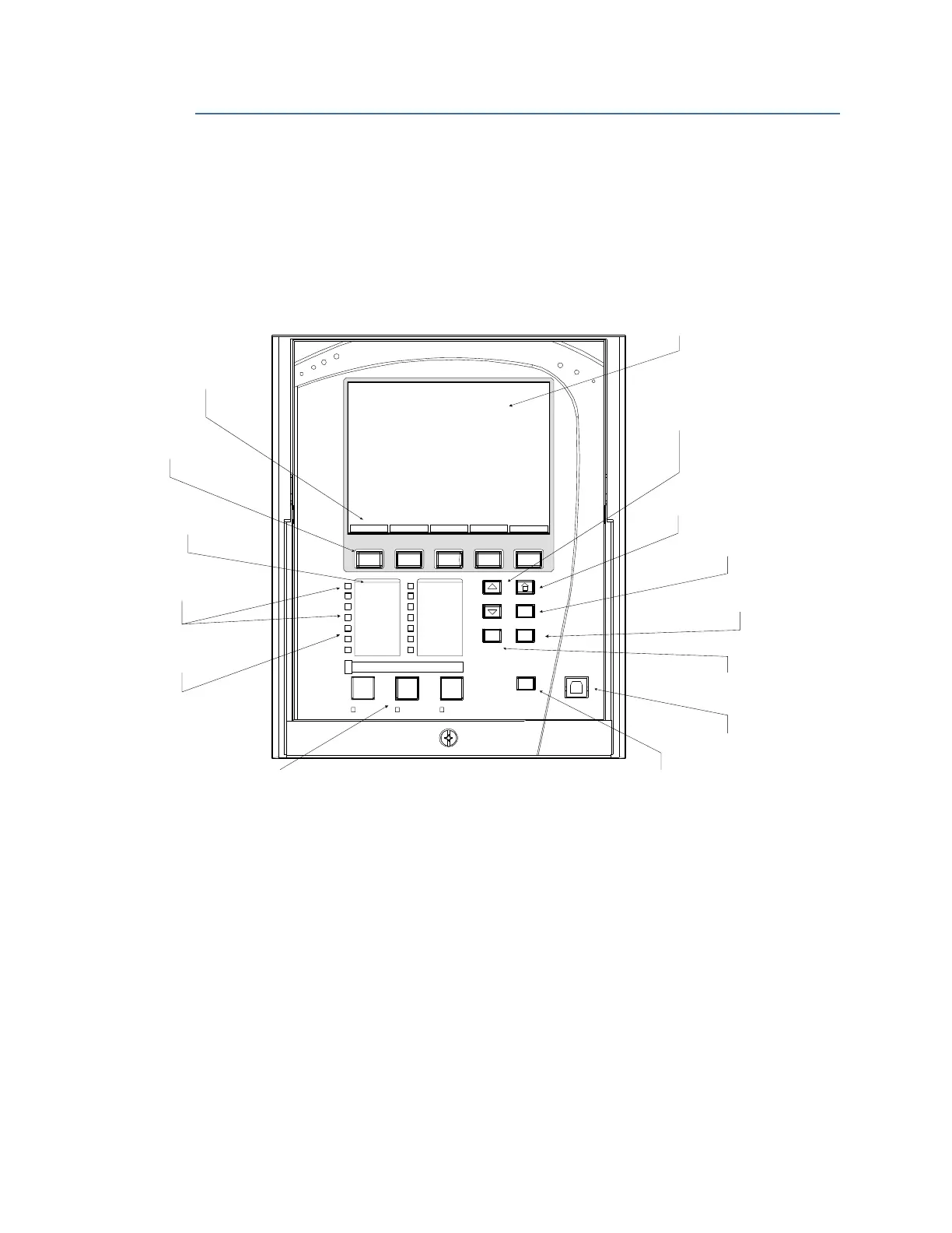
Front Control Panel Interface
The relay provides an easy to use faceplate for menu navigation using 5 navigation
pushbuttons and a high quality graphical display. Conveniently located on the panel is a
group of 7 pushbuttons for Up/Down value selection, Enter, Home, Escape, Help, and Reset
functions. The faceplate also includes 3 programmable function pushbuttons with LEDs.
Fourteen other status LEDs are available, 12 of which are programmable.
Figure 3-1: 869 Front Control Panel
Graphical Display Pages
The front panel liquid crystal display (LCD) allows visibility under various lighting conditions.
When the keypad and display are not being used and there are no active Targets, the
Home screen with system information is displayed after a user-defined period of inactivity.
Pressing the Escape key during the display of the default message, returns the display to
the previous display screen. Any Trip, Alarm, or Pickup operation causing a new active
Target is displayed immediately, automatically overriding the Home screen.
ESCAPE
ENTER HELP
IN SERVICE
TRIP
ALARM
PICK UP
START INHIBIT
GROUND FAULT
HOT RTD
START
RESET
STOP F1
STOPPED
STARTING
LOCAL MODE
OVERLOAD
TARGETS STATUS METERING SETPOINTS RECORDS
Navigation
Pushbuttons
Menu tabs associated
with pushbuttons for
screen navigation
Pushbuttons for
setpoints, and Up/ Down
value selections
“HELP”:help with
setting selection
“ESCAPE”: return to
previous menu
“Home”:r
eturn to
Home or default screens
“ENTER”:enter selected
setting
“RESET”: reset latched targets,
LEDs, output relays
LEDs #1 and LED#4 (non-
programmable)
LED#2,LED#3,
and LEDs 5 to 14
(programmable)
Function PBs with LEDs
(programmable)
USB port
Display
LED labels
TEST MODE
MESSAGE
RUNNING

 Loading...


