2–8 869 MOTOR PROTECTION SYSTEM – INSTRUCTION MANUAL
MECHANICAL INSTALLATION CHAPTER 2: INSTALLATION
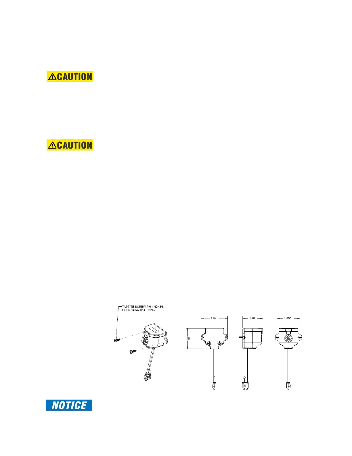
Arc Flash Sensor
The Arc Flash sensor houses the fiber optics and metal membrane that are used to detect
the arc flash. Two mounting screw holes are provided to affix the sensors to the panel.
CAUTION:
If the 8 Series is used in the computation for reducing the Hazard Reduction Category
code, operands for sensor failures must be assigned to an auxiliary output relay which
must be connected into the control logic of the breaker equipment to ensure safe
operations when the output relay is asserted. In the event of this assertion, the Hazard
Reduction Category code cannot be maintained unless backup protection is continuing
to maintain it.
Sensor Fiber Handling
& Storage
CAUTION:
Arc Flash sensor fiber is pressure sensitive and must be handled carefully to avoid
damage. Read the following guidelines fully before proceeding.
Care must be taken when handling the Arc Flash sensor fiber, which can be damaged if
twisted, bent, or clamped tightly during installation.
• Do not bend sensor fiber sharply, or with a radius of less than 25 mm (1 inch). Sharp
bends can dam
age the fiber. Do not pull or tug loops of sensor fiber, as sharp bends
may result.
• Do not clamp sensor fiber tightly during installation. Sensor fiber should be held in
pl
ace loosely for the best long-term performance. Avoid over-tightening ties which
may deform or break the sensor fiber.
• Do not pull or tug sensor fiber with force, as this may cause internal damage or
separat
e the fiber from the cable connector.
• Do not twist the sensor fiber, as twisting can damage the fiber resulting in
subst
andard performance.
• Do not attach sensor fiber directly to the bus.
• Avoid surface temperatures above 70 °C or 158 °F to prolong the life of the fiber.
• Secure all sensor fibers (loosely but securely) away from any moving parts.
• Use the factory-provided dust caps on all Arc Flash sensor fiber and connectors when
not in use,
to avoid dust contamination in the transceiver and sensor plugs.
Sensor Installation
Figure 2-10: AF Sensor - front, side and top view
FAST PATH:
Review the sensor fiber handling guidelines above.

 Loading...


