CHAPTER 4: SETPOINTS MONITORING
869 MOTOR PROTECTION SYSTEM – INSTRUCTION MANUAL 4–307
Speed
The 869 is capable of measuring the motor speed. Any of the input contacts can be used to
read the pulses from the input source. The source of the pulses can be an inductive
proximity probe or Hall Effect gear tooth sensor. The probe could be powered from a power
supply with a maximum of 48 VDC. The speed algorithm calculates the number of pulses in
the window length (WL) and converts it into an RPM value. A minimum pulse width of 10%
of a revolution is required to detect a pulse from the pulse source.
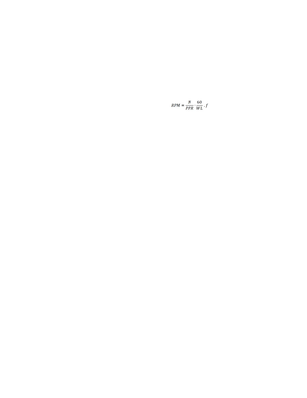
The following equation is used to calculate the speed based on the detection of the
number
of pulses ‘N’ during window length WL.
Where:
N – number of pulses during time defined by the setpoint Cal. Window
PPR – pulses per revolution defined by
setpoint PULSES PER REV (PPR)
f – system frequency defined under Setpoints\System\Power System
WL – calculated window length in cycles is defined as
WL = (60 x f) / (PPR x 50)
This element has two modes of speed: under speed and
over speed which is defined by the
setpoint Direction.
In the under speed mode, a trip and alarm is configured so that the machine must be at a
cer
tain speed within a set period of time from starting. The trip and alarm features are
configured so that the specified speed (Trip Pickup or Alarm Pickup) must be reached in the
specified time (Trip delay or Alarm Delay) otherwise the element operates. Initially, the time
delay begins when the machine starts rotating and resets when the desired speed is
reached. Once the machine is running with the rated speed and then that speed drops
below the set threshold, the time delay restarts and the designated output contact will
operate if the machine fails to reach the set speed in the allotted time.
In the over speed mode, the tachometer trip and alarm features are configured so that if
t
he specified speed (Trip Pickup or Alarm Pickup) is exceeded for the specified time (Trip
delay or Alarm Delay), the element operates. Initially, the time delay begins when the
machine speed exceeds the pickup value resets when the speed drops below the pickup.
Path:
Setpoints > Monitoring > Speed
TRIP FUNCTION
Range: Disabled, Trip, Configurable
Default: Disabled
This setting enables the Speed protection Trip functionality.
INPUT
Range: Off, Any Digital Input
Default: Off
Any of the digital input contacts can be used to read the pulses from the input source.
For example, an inductive proximity probe or Hall Effect gear tooth sensor may be used
to sense the key on the motor. The probe can be powered by the +24 V from the input
switch power supply. The NPN transistor output can be sent to one of the digital inputs.

 Loading...


