2–20 869 MOTOR PROTECTION SYSTEM – INSTRUCTION MANUAL
ELECTRICAL INSTALLATION CHAPTER 2: INSTALLATION
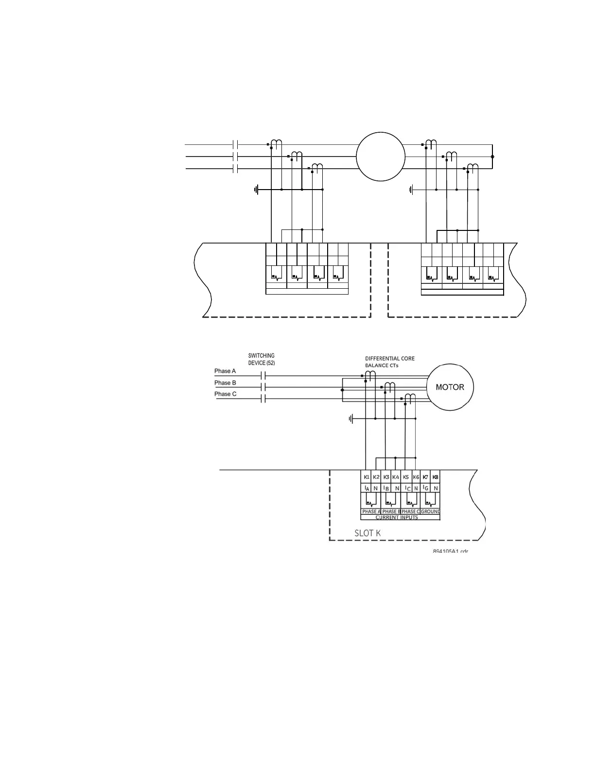
Differential CT Inputs
Wiring diagrams for two differential input options are depicted in the following figures.
Figure 2-22: Internal Summation Percent Differential Wiring
Figure 2-23: Core Balance Percent Differential Wiring
J1 J2 J3 J4 J5 J6 J7 J8
CURRENT INPUTS
SLOT J
PHASE A PHASE B PHASE C GROUND
I
B
N
I
C
I
G
I
A
NN
NEUTRAL SIDE CTsTERMINAL SIDE CTs
N
MOTOR
Phase A
Phase B
Phase C
SWITCHING
DEVICE (52)
K1 K2 K3 K4 K5 K6 K7 K8
CURRENT INPUTS
PHASE A PHASE B PHASE C GROUND
I
B
N
I
C
I
G
I
A
NNN
SLOT K
89$1.cdr

 Loading...


