CHAPTER 2: INSTALLATION ELECTRICAL INSTALLATION
869 MOTOR PROTECTION SYSTEM – INSTRUCTION MANUAL 2–19
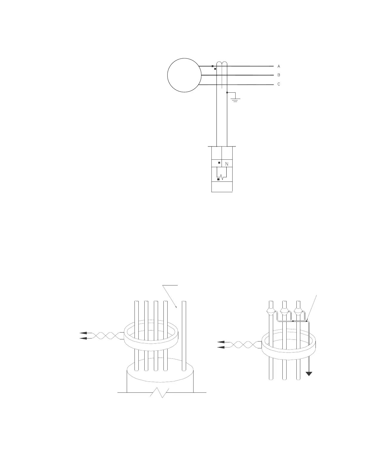
Figure 2-20: Sensitive Ground Current Input Connections
Zero-Sequence CT Installation
The figure below shows the various CT connections and the exact placement of a Zero
Sequence current CT, so that ground fault current can be detected. Twisted pair cabling on
the Zero Sequence CT is recommended.
Figure 2-21: Zero Sequence (Core Balance) CT Installation
894078A2.cdr
K7 K8
MACHINE
SENSITIVE
GROUND
I
sg
SENSITIVE GROUND INPUT
WITH ZERO SEQUENCE CT
GE 50:0.025
core-balance CT
Ground connection to neutral
must be on the source side
UNSHIELDED CABLE
LOAD
ABCN G
Ground
outside CT
Source
LOAD
SHIELDED CABLE
996630A5
AB C
Source
To ground;
must be on
load side
Stress cone
shields

 Loading...


