4–370 869 MOTOR PROTECTION SYSTEM – INSTRUCTION MANUAL
TESTING CHAPTER 4: SETPOINTS
Testing
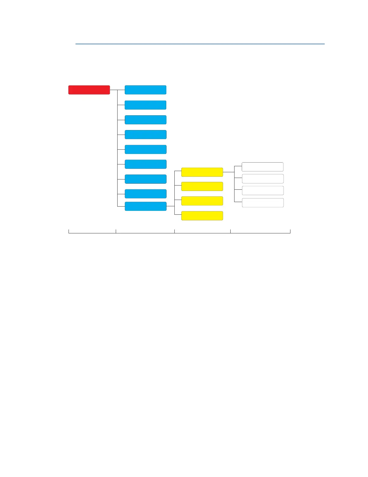
Figure 4-149: Testing Display Hierarchy
Main Menu
Path:
Setpoints > Testing
•Simulation
•Test LEDs
• Contact Inputs
•Output Relays
The 8 Series can simulate current and voltage inputs with the selections available under
the
Simulation feature. Other test operations are also possible such as LED lamp test of
each color, contact input states and testing of output relays.
Simulation
Path:
Setpoints > Testing > Simulation
•Setup
•Pre-Fault
•Fault
•Post-Fault
The Simulation feature is provided for testing the functionality of the 8 Series in response
t
o programmed conditions, without the need of external AC voltage and current inputs.
First time users will find this to be a valuable training tool. System parameters such as
currents, voltages and phase angles are entered as setpoints. When placed in simulation
mode, the relay suspends reading actual AC inputs, generates samples to represent the
programmed phasors, and loads these samples into the memory to be processed by the
Pre-Fault
Setpoints
Device
System
Inputs
Outputs
Protection
Monitoring
Control
FlexLogic
Level 1 Level 2 Level 3 Level 4
Setup
Testing
Simulation
Test LEDs
Contact Inputs
Output Relays
Fault
Post-Fault

 Loading...


