CHAPTER 2: INSTALLATION MECHANICAL INSTALLATION
869 MOTOR PROTECTION SYSTEM – INSTRUCTION MANUAL 2–3
Mounting
The unit can be mounted two ways: standard panel mount or optional tab mounting, if
required.
• S
tandard panel mounting:
From the front of the panel, slide the empty case into the cutout. From the rear of the
panel, sc
rew the case into the panel at the 8 screw positions (see figures in Standard
panel mount section).
• Option
al tab mounting:
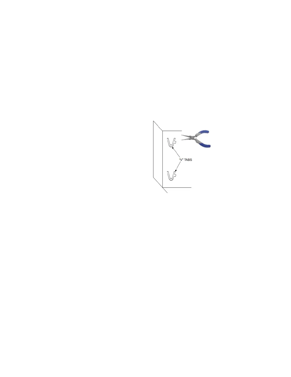
The “V” tabs are located on the sides of the case and appear as shown in the
follow
ing figure. Use needle nose pliers to bend the retaining "V" tabs outward to
about 90°. Use caution and do not bend and distort the wall of the enclosure adjacent
to the tabs. The relay can now be inserted and can be panel wired.
Figure 2-3: “V” Tabs Located on Case Side

 Loading...


