| 114 | 6 Repair | CARDIOHELP System |
Service Manual | 3.3 | EN | 05
Copyright Maquet Cardiopulmonary GmbH
5 Carefully lift up the sensor PCB.
Sensor PCB connections
CAUTION!
The wires of soldered connectors can be bent very easily.
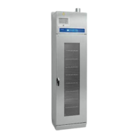
6 Disconnect the DIGIFLOW connection [3].
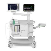
7 Unscrew the screws [4] of DIGIFLOW PCB.
DIGIFLOW PCB
8 Replace the DIGIFLOW PCB using a torque of 0.2 Nm and Loctite 270.
CAUTION!
Make sure that the contact between DIGIFLOW PCB and the heat conductive foil is sealed with silicone
(Momentive TSE397).
CAUTION!
Make sure that no silicone is in contact with the connector.
9 Reconnect the DIGIFLOW connection [3].
10 Carefully attach sensor PCB and affix it.
11 Reconnect motor cable [2] and fan drive cable [1].
12 Screw in all decorative slotted nuts with the special socket wrench.
13 Close the device (⇨ "Closing the Device", page 110).
14 Carry out a complete inspection (⇨ "Inspection", page 33).
u DIGIFLOW PCB replaced.
u Inspection after repair has been carried out.
6.10 Replacing Battery PCB
Requirements
Service training part 2
CAUTION!
ESD-sensitive components
To prevent damage to ESD-sensitive components, an ESD-protected environment must be set up.

 Loading...