| CARDIOHELP System | 6 Repair | 129 |
Service Manual | 3.3 | EN | 05
Copyright Maquet Cardiopulmonary GmbH
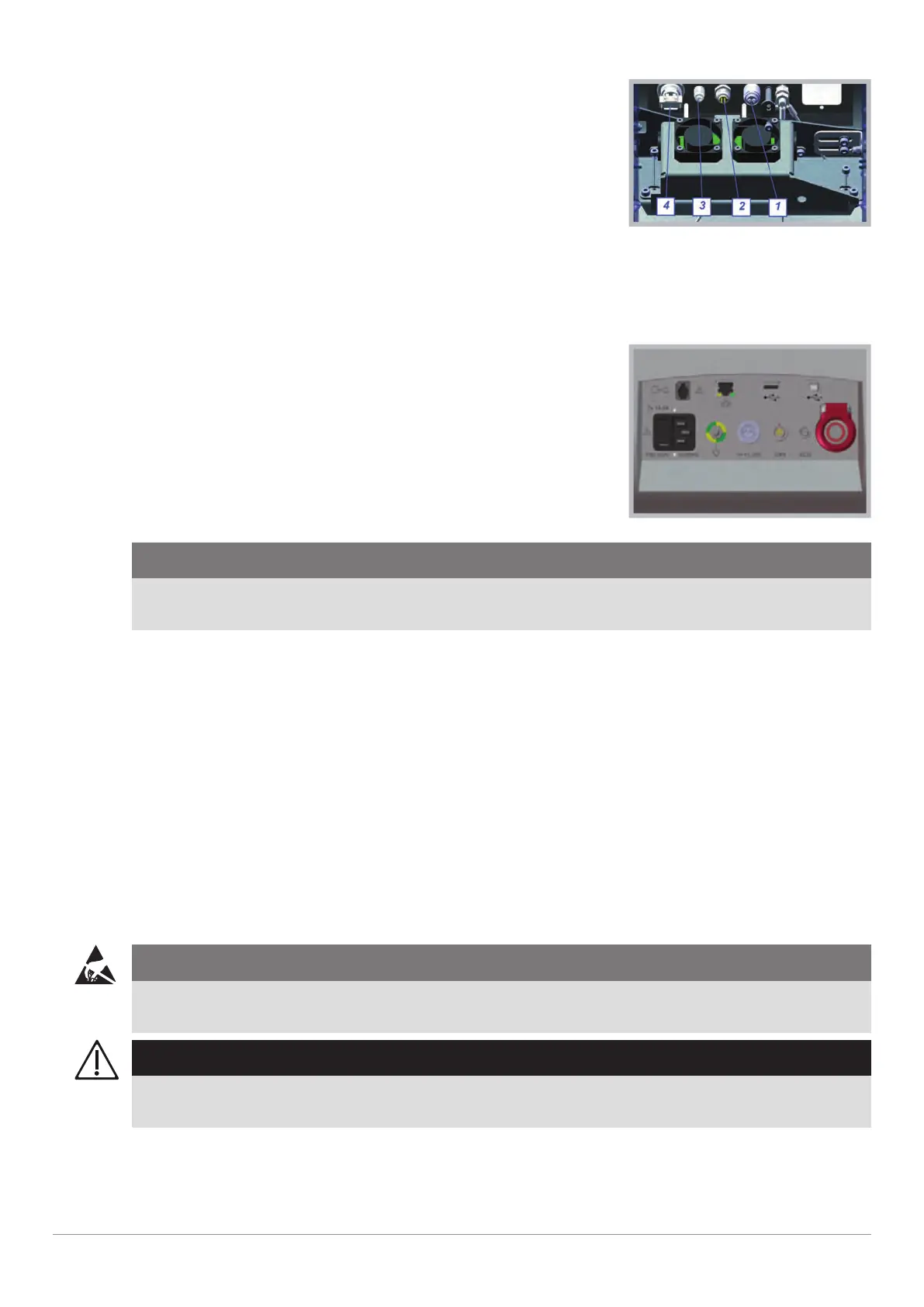
3 Disconnect the required cabel [1 … 4] from HMI PCB.
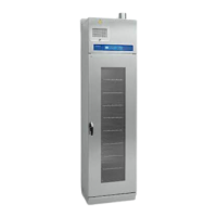
Mains power supply
1 DC device connector
2 CAN connector
3 ECG connector
4 Emergency mode button
4 Replace the damaged female connector with the adequate spark
plug wrench. See above which tools are required.
Front connections
CAUTION!
Do not touch the PCB‘s with the wrenches, because they will be damaged.
Pay attention to the correct position of the red dots and the connectors will not rotate.
5 Connect the female connector at HMI PCB.
6 Assemble the battery housing (⇨ "Assemble Battery Housing", page 117).
7 Close the device (⇨ "Closing the Device", page 110).
8 Carry out a complete inspection (⇨ "Inspection", page 33).
u DC device connector replaced.
u CAN connector replaced.
u ECG connector replaced.
u Emergency mode button replaced.
u Inspection after repair has been carried out.
6.19 Replacing Equipotential Bonding Pin
Requirements
Service training part 2
CAUTION!
ESD-sensitive components
To prevent damage to ESD-sensitive components, an ESD-protected environment must be set up.
WARNING!
To finish the task, the following step must be carried out in order to ensure error-free use.
n Carrying out the inspection (⇨ "Inspection", page 33).
1 Open the device (⇨ "Opening the Device", page 108).