1-24 ● Connection of signals
1.5.2 Overview
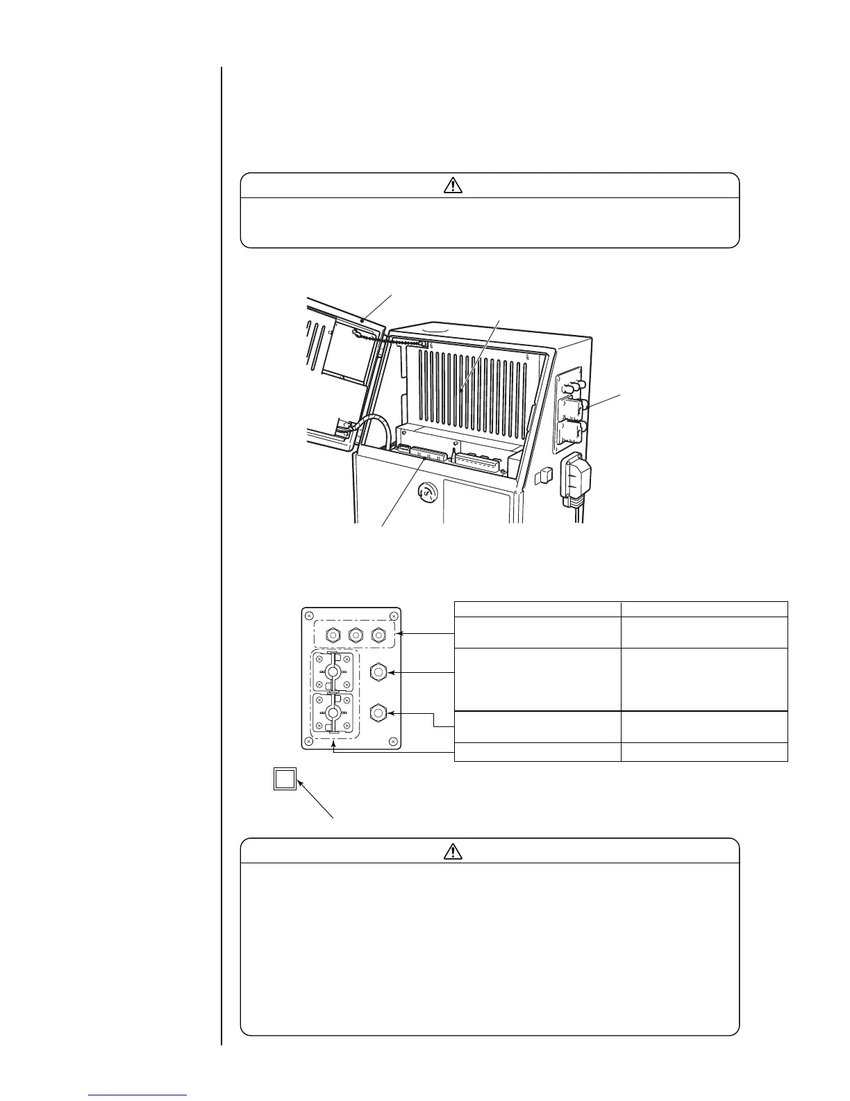
As for wiring of the input-output lines, open the operation panel cover and draw the
lines from the ports on the side, and connect them to the external connection terminal
blocks 1, 2 and the external communication connector inside.
Caution
Be sure to turn off the power when performing the wiring.
Keep the operation panel cover closed for normal use.
Terminal blocks 1, 2 and
communication connector
Operation panel cover
Electrical component cover
Ports
Name Cable outer diameter range
For print terget detector/
φ3.5 to 7 (M12)
encoder
For reciprocative print,
printing / print completed,
φ4.5 to 10 (M16)
stop printing, online and
remote signals
For ready, fault,
φ4.5 to 10 (M16)
warning
For external communication φ3.5 to 10
( ) indicates a tightening nut.
Power switch
Caution
Use the cables of the outer diameter range specified above. Securely tighten the
tightening nuts of the ports.
In addition, do not bundle weak-current and heavy-current signals together inside
and outside the equipment so that a weak-current signals (terminal block 1, a
connection signal to the external communication connector) will be least influenced
by noise from a heavy-current signals (a connection signal to the power supply and
the terminal block 2). In particular, the cables for the print terget detector, stop
printing signals, power supply and printable signals should never be bundled
together or wired in the same duct.
¡
Ports
 Loading...