1-28 ● Connection of signals
1.5.3-1 Ready output signal
The following describes the wiring of the signal that is outputted to the outside for
the purpose of indicating that the IJ printer is ready state.
(To prevent a print target from traveling without being printed, this signal is used,
for instance, to stop the conveyor when the IJ printer cannot perform printing.)
When this signal is connected, set the ready output switch to 3.
(See Section 1.5.4, Using the Ready Output Selector Switch).
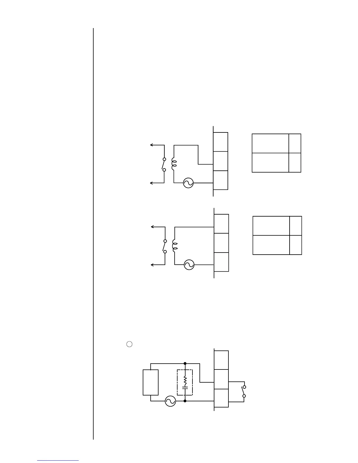
(a) When using the NO contact (make contact)
1.5.3 Connection of various signal
(b) When using the NC contact (break contact)
For both the NO and NC contacts, the maximum capacity is 30 VAC/0.5 A or 30
VDC / 1 A. If any load having a greater capacity is used, furnish a separate
relay in between.
Further, if a motor, relay, or other inductive load is employed, a counter-
electromotive force may
be generated to reduce the useful contact life. Therefore, be sure to provide
contact protection.
Typical contact protection methods are indicated below.
1 Applicable to CR system (AC, DC)
The suggested values for capacitor C and resistor R are as follows.
C: 0.5 to 1μF, no polarity
R: 0.5 to 1 Ωper 1 V
The withstanding voltages of the capacitor and resistor must be at least two times
as high as the employed voltage.
 Loading...