Graph ics Co mm an d Set
graphics window and the graphics object area coincide, and the boundaries of
the graphics object area determine the limits of the graphics picture. Any
portion of the graphics picture extending beyond the graphics object area is not
drawn on the page.
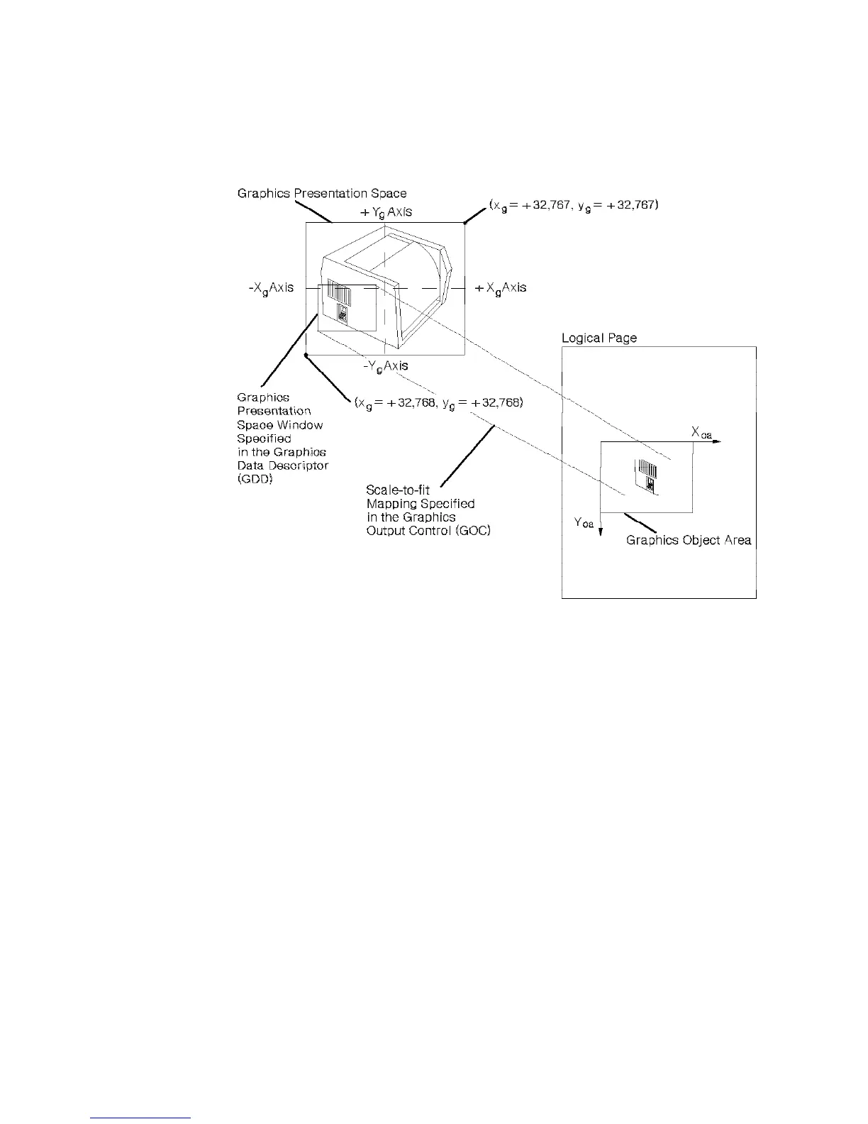
Figure 20. Center-and-Trim Mapping
Position and Trim Mapping: The upper left-hand corner of the graphics window
is mapped to the graphics object area using the specified offset and presented at
the specified scale. Any portion of the picture that goes outside the graphics
object area is clipped to the area boundary. Figure 21 shows the result of
position-and-trim mapping. For this example, the graphics window is shown
smaller than a previously defined graphics picture. This picture is to be placed
on the physical medium. The parameters in the Graphics Data Descriptor
specify the size of the graphics window. The parameters in the Graphics Area
Position and the Graphics Output Control specify the size and location of the
graphics object area on the physical medium.
If the graphics object area is smaller than the graphics window, a portion of the
graphics picture is eliminated. The top-left corner of the graphics window is
either coincident with the top left corner of the graphics object area, or it is offset
from the top left corner of the graphics object area by a distance specified in the
Graphics Output Control. Only the portion of the picture contained within the
overlapping areas of the graphics window and the graphic object area will be
drawn. The printer trims (eliminates) the portion of the graphics picture outside
this area.
90 6400 IPDS
 Loading...