3
1
PANEL DESCRIPTION
!0 MANUAL NOTCH KEY [MNF/ADJ] (p. 83)
➥ Push momentarily to turn the manual notch func-
tion ON and OFF in SSB, CW and AM modes.
• “ ” appears on the display when the function is ac-
tivated.
➥ Push and hold for 1 sec. to enter the manual
notch filter set mode.
✔
What is the notch function?
The notch function is a narrow DSP filter that removes inter-
fering tones from CW or AM signals while preserving the de-
sired signal's frequency response.
!1 AUTO NOTCH/VOICE RECORDER KEY
[ANF/
•
REC]
➥ Push momentarily to turn the auto notch function
(ANF) ON and OFF in SSB, AM, FM modes.
(p. 82)
• “ ” appears on the display when the function is ac-
tivated.
➥ Push and hold for 1 sec. to record the received
signal’s audio. (p. 95)
!2 SPCH/LOCK KEY [SPCH/LOCK]
➥ Push momentarily to have the frequency, etc. an-
nounced by the speech synthesizer. (p. 34)
•The parameters to be announced can be selected in
the miscellaneous (others) set mode. (p. 134)
➥ Push and hold for 1 sec. to toggle the dial lock
function ON and OFF. (p. 37)
•The dial lock function electronically locks the main
dial.
• “ ” appears while the dial lock function is activate.
!3 MICROPHONE CONNECTOR (p. 10)
Modular-type microphone connector—Accepts the
supplied microphone (HM-151).
•The optional OPC-589 can be used to connect an 8-pin
microphone such as the SM-20, if desired.
•A microphone connector is also available on the rear
panel. DO NOT connect 2 microphones simultaneously.
!4
UP/DOWN (BAND) KEYS
[Y(
BAND
)]/[
Z
(
BAND
)]
➥ Push momentarily to select a frequency band or
TV channel.
➥ Push and hold
[Y(
BAND
)]
for 1 sec. to toggle the
simple band scope display ON and OFF.
➥ Push and hold
[Z(
BAND
)]
for 1 sec. to toggle the
multi-function meter display ON and OFF.
!5 MAIN DIAL TENSION LATCH
Selects the main dial drag.
•Three positions are available. Upper setting turns on
clicks as the dial is turned..
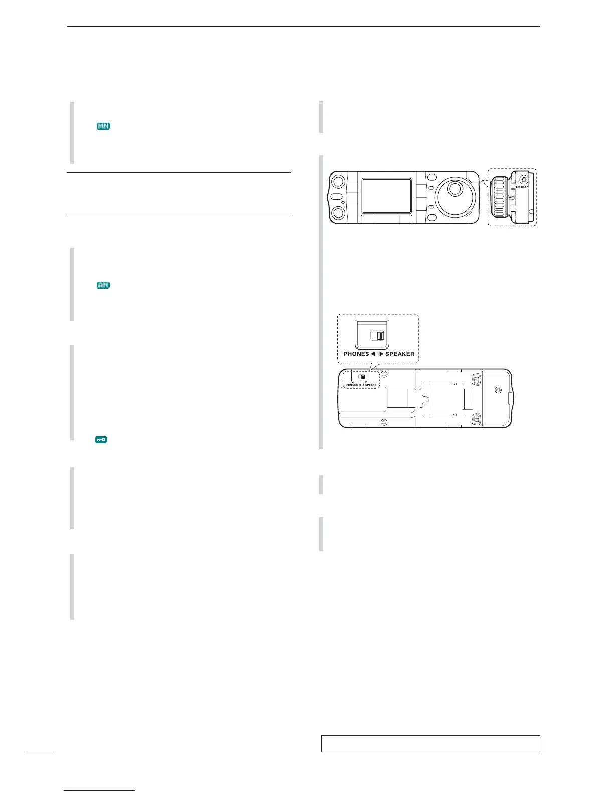
!6 HEADPHONE JACK [PHONES] (p. 18)
Accepts headphones with 8–16 impedance.
•When headphones are connected, no receive audio
comes from the speaker.
•When the PHONES/SPEAKER switch on the back of the
front panel is set to the [SPEAKER] position, an external
speaker can be used instead of headphones. This is
convenient for mobile or outdoor operation.
!7 MAIN DIAL [DIAL]
Changes the displayed frequency and selects val-
ues for selected set mode items, etc.
!8 RECEIVE/TRANSMIT INDICATORS [RX]/[TX]
➥[RX]: Lights green in receive mode and when
squelch is open.
➥[TX]: Lights red while transmitting.
 Loading...