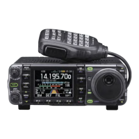
CONTROLLER TO IC-7000
FE FE 70 E0 Cn Sc Data area FD
Preamble code (fixed)
Transceiver’s default address
Controller’s default address
Command number
(see table below)
Sub command number
(see table below)
BCD code data for frequency
or memory number entry
End of message code (fixed)
OK MESSAGE TO CONTROLLER
FE FE 70 E0 FB FD
Preamble code (fixed)
Transceiver’s default address
Controller’s default address
OK code
(fixed)
End of message code (fixed)
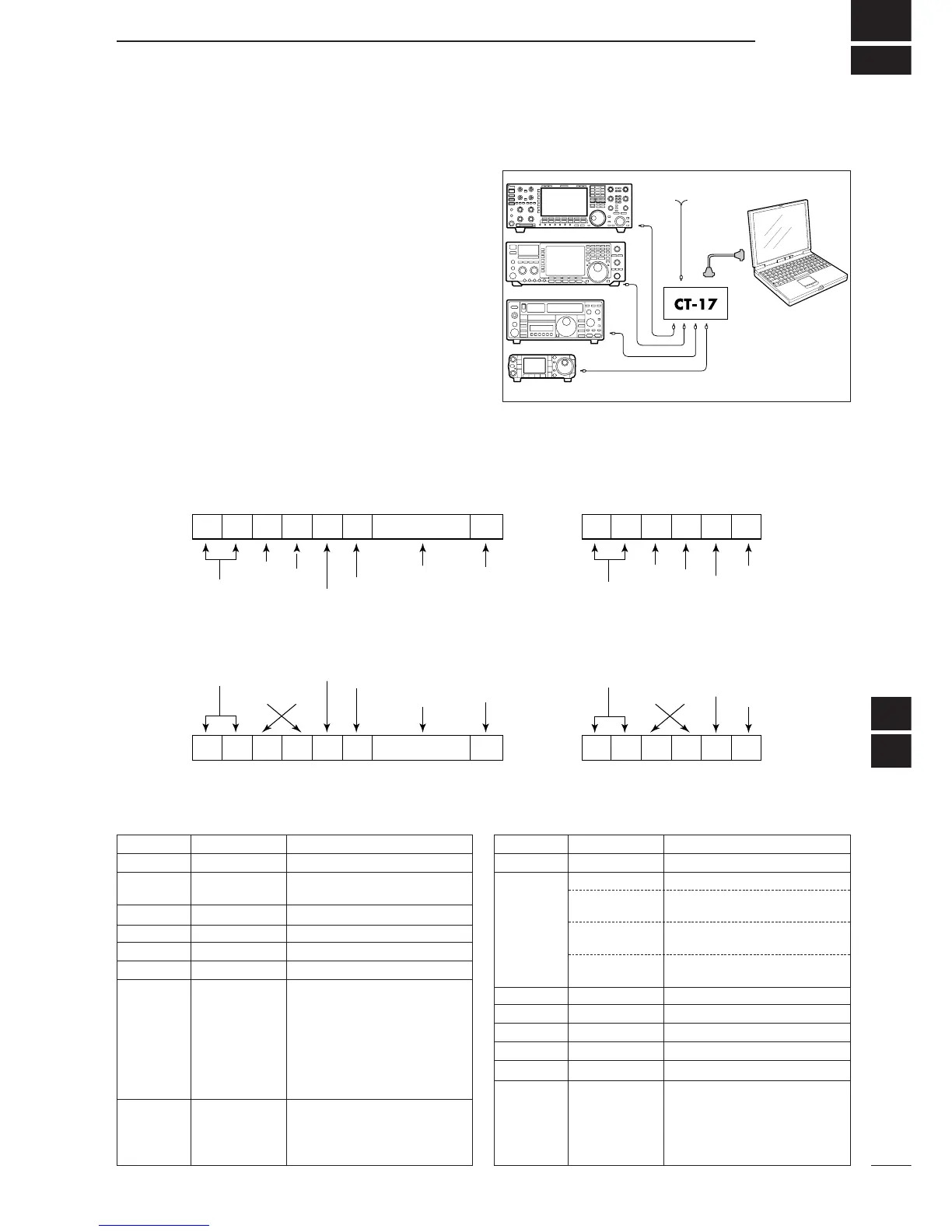
NG MESSAGE TO CONTROLLER
FE FE 70 E0 FA FD
NG code
(fixed)
IC-7000 TO CONTROLLER
FE FE E0 70 Cn Sc Data area FD
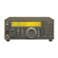
D CI-V connection example
The transceiver can be connected through an optional
CT-17
CI
-
V LEVEL CONVERTER
to a personal computer
equipped with an RS-232C port. The Icom Communi-
cation interface-V (CI-V) controls the following func-
tions of the transceiver.
Up to four Icom CI-V transceivers or receivers can be
connected to a personal computer equipped with an
RS-232C port. See p. 82 for setting the CI-V condition
using initial set mode.
D Data format
The CI-V system can be operated using the following
data formats. Data formats differ according to com-
mand numbers. A data area is added for some com-
mands.
Personal
computer
mini-plug cable
IC-7000
9–15 V DC
■ Remote jack (CI-V) information
16
17
D C
ommand table
00 — Send frequency data
01 Same as Send mode data
command 06
02 — Read band edge frequencies
03 — Read operating frequency
04 — Read operating mode
05 — Set operating frequency
06 00 Select LSB
01 Select USB
02 Select AM
03 Select CW
04 Select RTTY
05 Select FM
07 Select CW-R
08 Select RTTY-R
07 — Select VFO mode
00 Select VFO A
01 Select VFO B
A0 Equalize VFO A and VFO B
07 B0 Exchange VFO A and VFO B
08 — Select memory mode
0001–0105* Select memory channel
*P1=0100, P2=0101
0106, 0107 Select the call channel
(C1=0106, C2=0107)
A0 Set the bank number
(1=A, 2=B, 3=C, 4=D, 5=E)
09 — Memory write
0A — Memory to VFO
0B — Memory clear
0C — Read offset frequency
0D — Set offset frequency
0E 00 Scan stop
01 Programmed/memory scan start
02 Programmed scan start
22 Memory scan start
23 Select memory scan start
Command Sub command Description Command Sub command Description
 Loading...