3
25
BASIC OPERATION
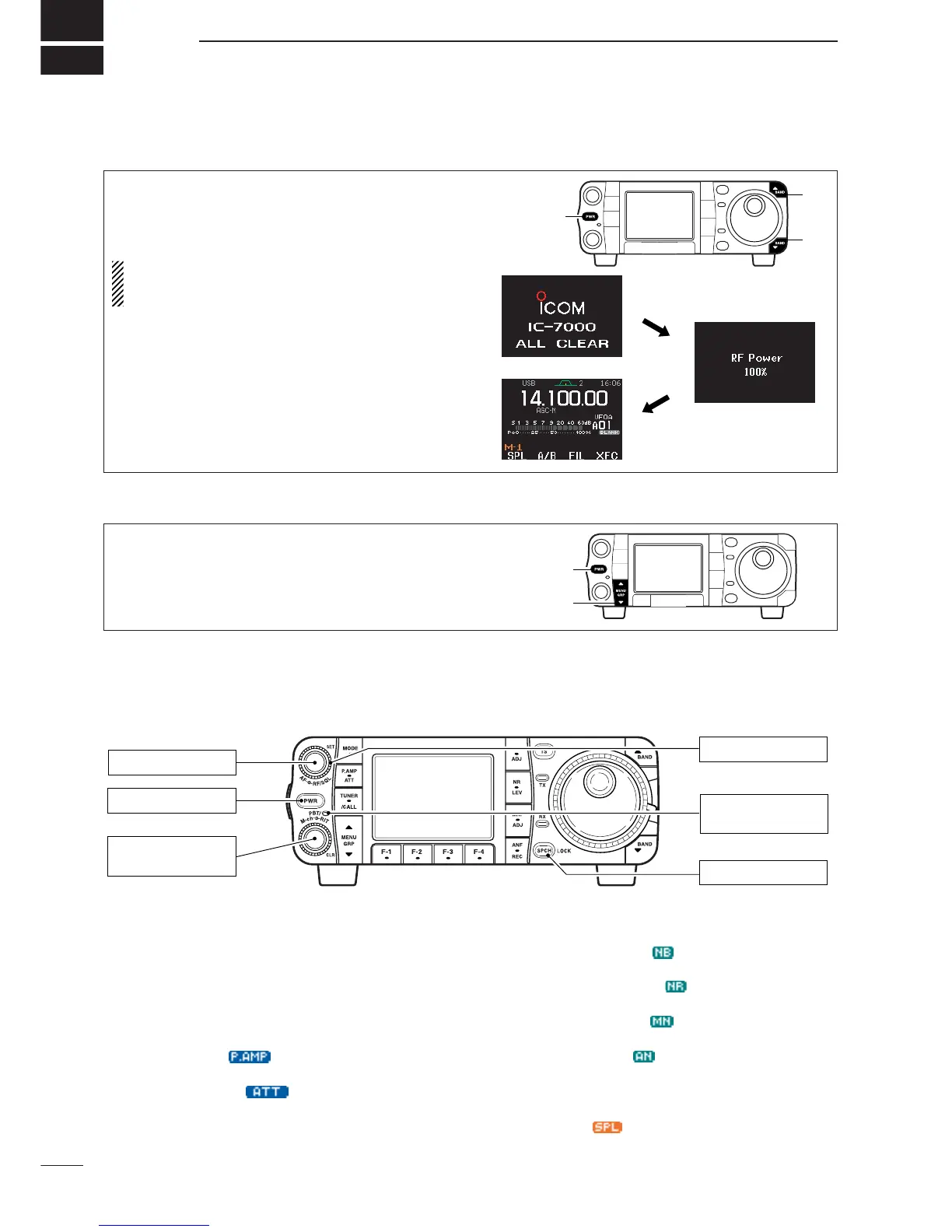
■ When first applying power (CPU resetting)
Before first applying power, make sure all connec-
tions required for your system are complete by refer-
ring to Chapter 2. Then, reset the transceiver using
the following procedure.
Resetting CLEARS all programmed contents in
memory channels and returns programmed values
in set mode.
q Make sure the transceiver power is OFF.
w While pushing [
Y
(
BAND
)] and [
Z
(
BAND
)], push
[PWR] for 1 sec. to start resetting.
• The internal CPU is reset.
•The display changes to ‘ALL CLEAR,’ ‘RF power 100%’
and ‘Initial frequency and Mode’ as shown at right.
The transceiver’s
initial frequency and mode
[RF/SQL]: Center
[LOCK]: OFF
[POWER]: OFF
[AF]: Max. CCW
[PBT]: Center
(Push and hold for 1 sec.)
[PBT/M-ch/RIT]
: PBT
(indicator lights)
CCW : counterclockwise
D Menu resetting (
M
-
1
)
Turn power ON, then check the display. If any of the
following indicators appear, turn them OFF as follows:
•Tuning step indicators,
Z
, (SSB, CW or RTTY):
Push [TS].
•MHz tuning step indicator,
Z
, (FM, WFM or AM):
Push [TS]
• 1 Hz frequency readout (SSB, CW or RTTY):
Push and hold [TS].
• Preamp indicator, :
Push [P.AMP/ATT]
• Attenuator indicator, :
Push [P.AMP/ATT]
• Noise blanker indicator, :
Push [NB/ADJ]
• Noise reduction indicator, :
Push [NR/LEV]
• Manual notch indicator, :
Push [MNF/ADJ]
• Auto notch indicator, :
Push [ANF/
•
REC]
• Memory mode indicator, MEMO:
Use [F-4
V/M
] in the
M
-
2
menu (p. 27).
• Split indicator, :
Use [F-1
SPL
] in the
M
-
1
menu (p. 91).
If you can’t figure out how to return to the menu
M
-
1
:
While pushing either [
Y
(
MENU
/
GRP
)] or [
Z
(
MENU
/
GRP
)], turn power ON.
•The other groups are also reset to
S
-
1
or
G
-
1
(Scope) in
this time.
After resetting the transceiver, set controls and
switches as shown in the diagram below.
■ Initial settings
 Loading...