13
1
PANEL DESCRIPTION
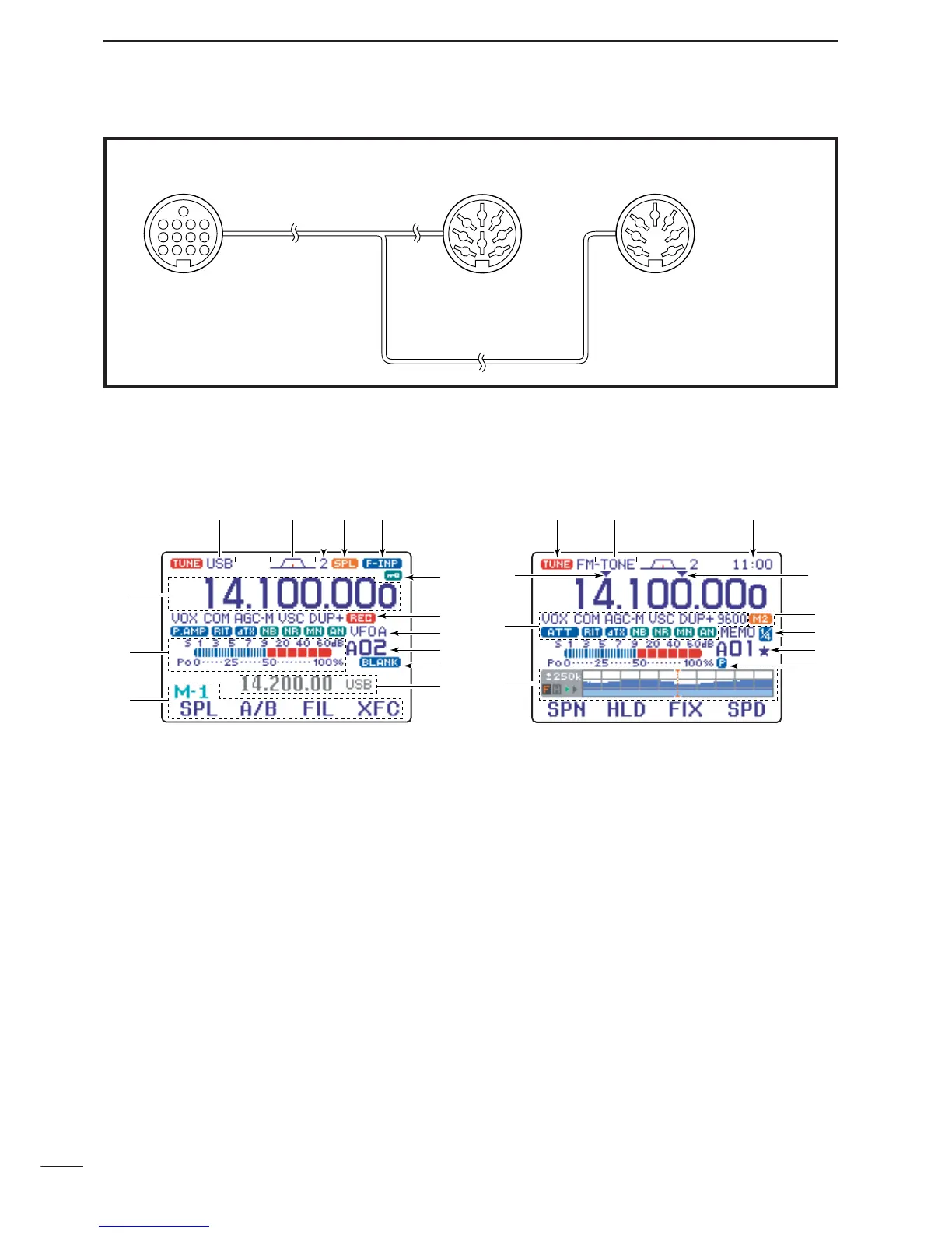
q FREQUENCY READOUT
Shows the operating frequency.
w METER READOUTS
➥ Shows received signal strength while receiving.
➥ Shows either transmit power meter (Po), SWR,
ALC or compression level meter (COM) while
transmitting.
e MULTI-FUNCTION KEY GUIDE
Indicates the function of the multi-function keys.
These alphanumeric readouts show a variety of in-
formation such as current functions of the “F” keys
[F-1] to [F-4].
r SPLIT FREQUENCY READOUT
Shows the transmit frequency during split operation.
t BLANK MEMORY INDICATOR
Appears when the displayed memory channel is not
programmed (blank channel).
• This indicator appears both in VFO and memory modes.
y MEMORY CHANNEL READOUT
Shows the selected memory channel or scan edge
channel.
•Memory bank indicator (A to E) appears to the left of
memory channel.
• This indicator appears both in VFO and memory modes.
u VFO/MEMORY INDICATORS
➥VFO A or B appears when VFO mode is selected;
MEMO appears when memory mode is selected.
i VOICE RECODER INDICATORS
REC appears when the digital voice recoder func-
tion is activated.
o LOCK INDICATOR
Appears when the dial lock function is activated.
!0 DIRECT FREQUENCY ENTRY INDICATOR (p. 29)
Appears when the transceiver is ready for direct fre-
quency entry.
•This indicator appears when [(F-INP)ENT] key on the
HM-151 is pushed.
 Loading...