2
15
INSTALLATION AND CONNECTIONS
■ Unpacking
After unpacking, immediately report any damage to the
delivering carrier or dealer. Keep the shipping cartons.
For a description and a diagram of accessory equip-
ment included with the IC-7000, see ‘Supplied acces-
sories’ on p. i-1 of this manual.
■ Selecting a location
Select a location for the transceiver that allows ade-
quate air circulation, free from extreme heat, cold, or
vibrations, and away from TV sets, TV antenna ele-
ments, radios and other electromagnetic sources.
The base of the transceiver has an adjustable stand
for desktop use. Set the stand to one of two angles de-
pending on your operating conditions. (see description
on right hand page)
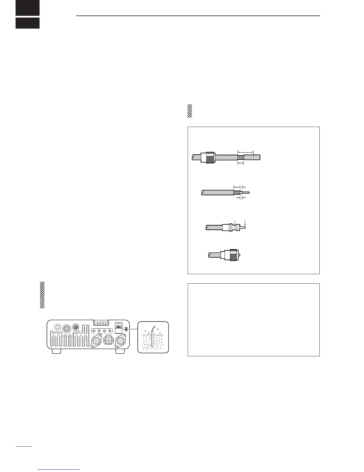
■ Grounding
To prevent electrical shock, television interference
(TVI), broadcast interference (BCI) and other prob-
lems, ground the transceiver through the GROUND
terminal on the rear panel.
For best results, connect a heavy gauge wire or strap
to a long, buried copper rod. Make the distance be-
tween the [GND] terminal and ground as short as pos-
sible.
R WARNING: NEVER connect the [GND] ter-
minal to a gas pipe or electric conduit, since the
connection could cause an explosion or electric
shock.
■ Antenna connection
For radio communications the antenna is of critical im-
portance for output power and sensitivity. Use well-
matched 50-ohm antennas and coaxial feedline. An
SWR (standing wave radio) of 1.5:1 or lower is recom-
mended when transmitting.
CAUTION: Protect your transceiver from lightning
by using a lightning arrestor.
ANTENNA SWR
Each antenna is tuned for a specified frequency
range and SWR increases outside that range. When
the SWR is higher than approx. 2.0 : 1, the trans-
ceiver’s power drops to protect the final transistors.
In this case, an antenna tuner is used to match the
transceiver and antenna. Low SWR allows full power
for transmitting even when using the antenna tuner.
The IC-7000 has an SWR meter to monitor the an-
tenna SWR continuously.
down. Strip the cable
jacket and soft solder.
body on and solder it.
body.
shown at left. Soft
ductor.
 Loading...