148
17
CONTROL COMMAND
17
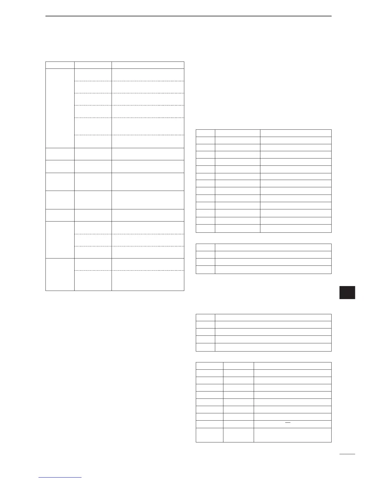
• Command table (continued)
D
To send/read memory contents
When sending or reading memory contents, additional code
as follows must be added to appoint the memory channel.
➥ Additional code: 0000–0102
(0100=P1, 0101=P2, 0102=Call)
D
Band stacking register
To send or read the desired band stacking register’s con-
tents, combined code of the frequency band and register
codes as follows are used.
For example, when sending/reading the oldest contents in
the 21 MHz band, the code “0703” is used.
• Frequency band code
• Register code
D
Codes for memory keyer contents
To send or read the desired memory keyer contents, the
channel and character codes as follows are used.
• Channel code
• Character’s code
1A 050114 Send/read NR level set
(0=0 to 15=15)
050115 Send/read VOX gain (0=0% to
255=100%)
050116 Send/read anti VOX gain (0=0% to
255=100%)
050117 Send/read VOX delay (0=0.0 sec.
to 20=2.0 sec.)
050118 Send/read DTMF speed set
(0=100 msec., 1=200 msec.,
2=300 msec., 3=500 msec.)
050119 Send/read Break-IN delay set
(20=2.0d to 130=13.0d)
06 Send/read SSB transmit band-
width (0=WIDE, 1=MID, 2=NAR)
07 Send/read DSP filter shape
(0= sharp, 1= soft)
08 Send/read manual notch filter1
bandwidth
(0=WIDE, 1=MID, 2=NAR)
09 Send/read manual notch filter2
bandwidth
(0=WIDE, 1=MID, 2=NAR)
0A Send/read 9600 bps mode set
(0=OFF, 1=ON)
1B 00 Set/read repeater tone frequency
(see p. 149 for details)
01 Set/read TSQL tone frequency
(see p. 149 for details)
02 Set/read DTCS code and polarity
(see p. 149 for details)
1C 00 Set/read the transceiver’s condi-
tion (0=Rx; 1=Tx)
01 Set/read antenna tuner condition
(0=OFF, 1=ON, 2=Start tuning or
while tuning)
Command Sub command Description
Code Frequency band Frequency range (unit: MHz)
01 1.8 1.800000– 1.999999
02 3.5 3.400000– 4.099999
03 7 6.900000– 7.499999
04 10 9.900000–10.499999
05 14 13.900000–14.499999
06 18 17.900000–18.499999
07 21 20.900000–21.499999
08 24 24.400000–25.099999
09 28 28.000000–29.999999
10 50 50.000000–54.000000
11 144 144.000000–148.000000
12 430 430.000000–450.000000
13 GENE Other than above
Code Registered number
01 1 (latest)
02 2
03 3 (oldest)
Code Channel number
01 M1
02 M2
03 M3
04 M4
CW: Clockwise, CCW: Counter Clockwise
Character ASCII code Description
0–9 30–39 Numerals
A–Z 41–5A Alphabetical characters
space 20 Word space
/ 2F Symbol
? 3F Symbol
, 2C Symbol
. 2E Symbol
^ 5E e.g., to send
BT
, enter ^4254
✱ 2A Inserts contact number (can be
used for 1 channel only)
 Loading...