SECTION 12—ELECTRONICS
Part No. 1125038 117 Pronto
®
M91™and M94™
1. Turntheadjustmentlocklevertoreleasethejoystickmountingtubefromthe
mountingbracket.
2. Removethejoystickfromthewheelchair.
3. Removethethreehexmountingscrews,spacersandlocknutsthatsecurethe
mountingbrackettothethreemountingholesonthearmframe.
NOTE:Themountingbracketismountedtotheinsideofthearmframe.
4. Repositionthemountingbracketontheoppositearmframe.
5. Usingthethreehexmountingscrews,spacersandlocknuts,securethemounting
brackettothethreemountingholesofthearmframe.
6. Ifnecessary,performthefollowingtorepositiontheadjustmentlock:
A. Slidetheadjustmentlockfromthemountingbracket.
B. Rotateadjustmentlock180°andslideadjustmentlockovertheoppositeendofthe
mountingbracket.
7. Slidejoystickmountingtubethroughthemountingbrackettothedesiredposition
andsecureadjustmentlocktotubebyturningleveronadjustmentlock.
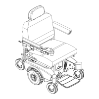
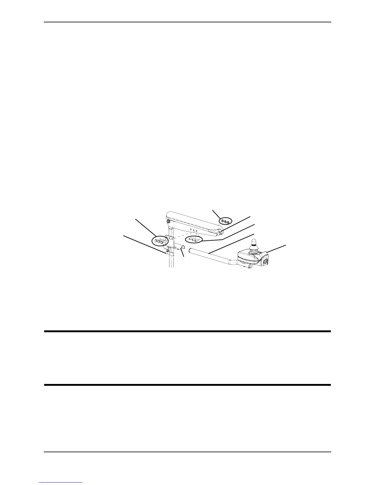
FIGURE 12.5 Repositioning the Joystick - Van Seat Model
Replacing the MKIV RII™ 80 AMP Controller
WARNING
DO NOT attempt to perform this procedure with any power supplied to the wheel
chair. The joystick and batteries MUST be disconnected prior to removing the
MKIV RII controller module. Otherwise, equipment damage and/or personal injury
may occur.
NOTE:Forthisprocedure,refertoFIGURE 12.6onpage118.
NOTE:TheMKIVRIIControllerModulehasfivecables,withconnectors.Thesecablesarefor
controloftheLeftandRightdrivemotors(cablesarelabeled),MKIVRIIJoystickcontrol,power
connectionforthebatteriesand(ifequipped)apowertakeofflead.
NOTE:Takenoteofpositionandorientationofthecontroller,cables,connectors,andmounting
hardwareforreinstallationofcontroller.
NOTE:MK
5
SPJ‐80joystick
shown.Allotherjoysticks
repositionthesameway.
Hex Mounting Screws
Locknuts
Adjustment Lock Lever
Joystick Mounting Tube
Mounting
Bracket
Spacers
Arm Frame
Joystick

 Loading...