IGNITION
COMPONENTS
COMPONENTS
Flywheel
The flywheel contains permanent magnets which
energize the charge coil, sensor coil, and alterna-
tor stator.
Once the flywheel exceeds a minimum
cranking RPM, the flywheel's magnetic lines of
force pass through the ignition plate components
to produce voltage
in
those circuits.
1
1. Permanent magnets
32278
Charge Coil
The charge coil contains many windings of wire
wrapped around a metal lamination.
Once the fly-
wheel exceeds a minimum cranking RPM, the fly-
wheel's magnetic lines of force pass through the
coil windings to produce voltage. The voltage
is
supplied to the power pack to operate the ignition
system.
1
1.
Charge coil
114
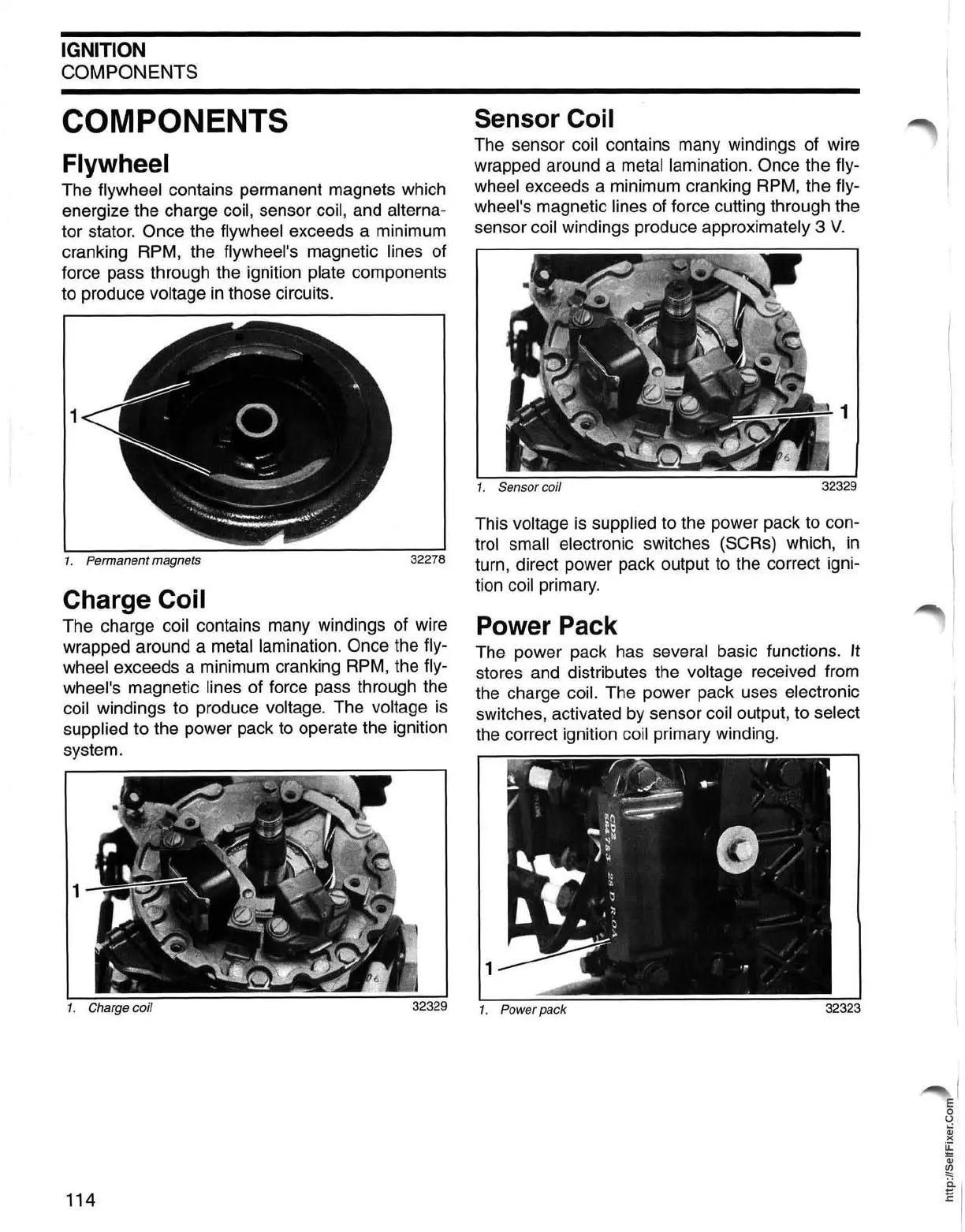
Sensor Coil
The sensor coil contains many windings of wire
wrapped around a metal lamination. Once the fly-
wheel exceeds a minimum cranking RPM, the fly-
wheel's magnetic lines of force cutting through the
sensor coil windings produce approximately 3
V.
1
1.
Sensor coil
This voltage
is
supplied to the power pack to con-
trol small electronic switches (SeRs) which,
in
turn, direct power pack output to the correct igni-
tion coil primary.
Power Pack
The power pack has several basic functions.
It
stores and distributes the voltage received from
the charge coil. The power pack uses electronic
switches, activated by sensor coil output, to select
the correct ignition coil primary winding.
1.
Power pack
 Loading...