MIDSECTION
SWIVEL BRACKET
TILLER MODELS
Slide
the actuator cam through the lower engine
cover. Place the bottom of the cam over the
grease fitting of the adjustment
lever and shaft.
Secure the actuator
cam
to the adjustment lever
and shaft with two screws, washers, and nuts.
Torque screws to 60-80
in.
Ibs.
(7-9 N·m).
1. Actuator cam
Position the actuator
cam
grommet
in
place
in
the
lower engine cover.
REMOTE MODELS
Secure the spacer lever and shift lever to the
adjustment
lever and shaft with two screws, plate
spacer, and nuts. Torque screws to 60 to 80
in.
Ibs.
(7
to 9 N·
m).
1. Shift lever
2. Spacer
ALL
MODELS
Install
the following:
•
Gearcase; refer to Gearcase REMOVAL AND
INSTALLATION
on
p.
260.
•
Powerhead; refer to Powerhead INSTALLA-
TION
- 25/30
on
p.
214.
246
SWIVEL BRACKET
Disassembly
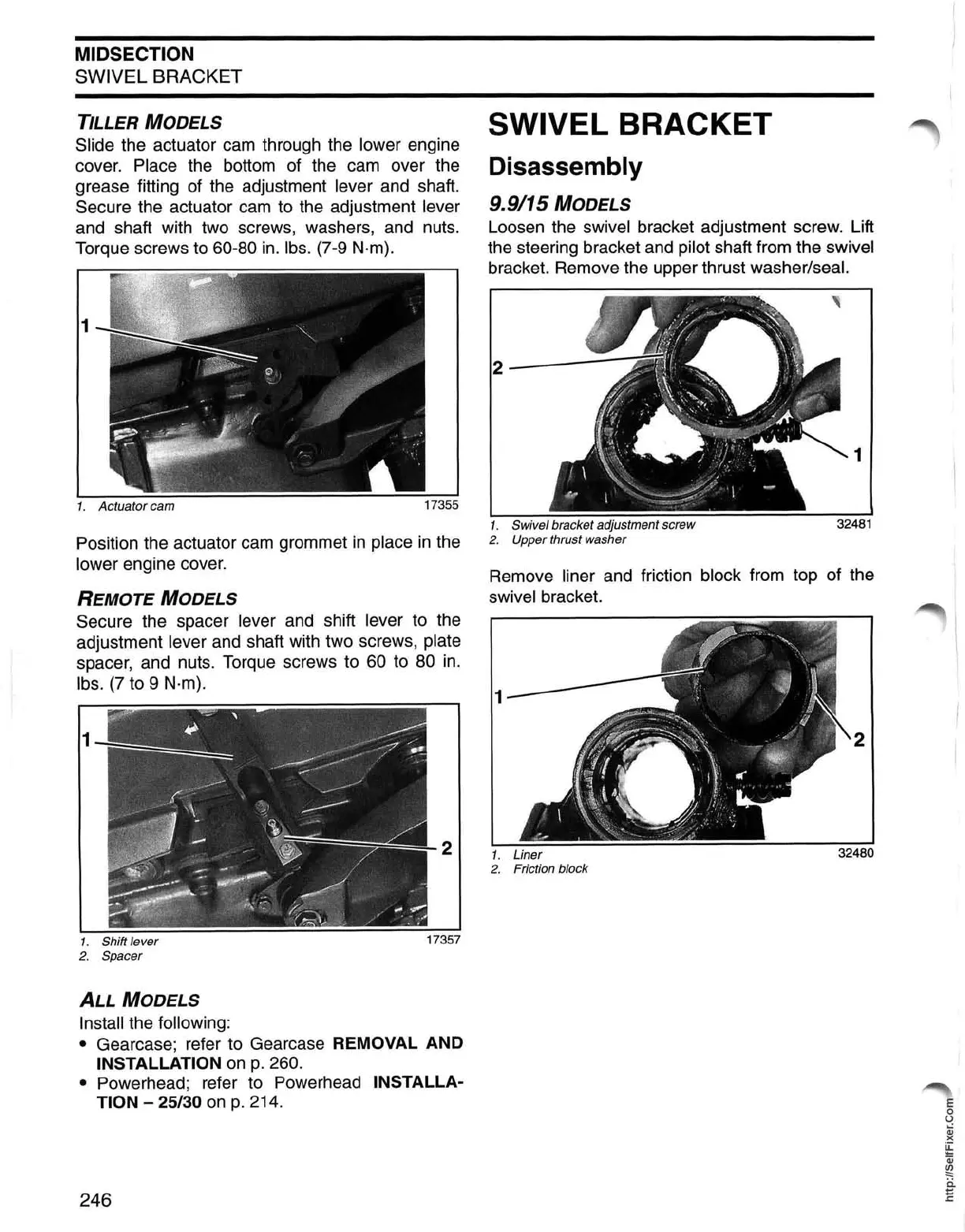
9.9/15 MODELS
Loosen the swivel bracket adjustment screw. Lift
the steering bracket and
pilot shaft from the swivel
bracket. Remove the upper thrust washer/seal.
,
2-------:;
1
1. Swivel bracket adjustment screw
32481
2.
Upper thrust washer
Remove liner and friction block from top of the
swivel bracket.
1.
Liner
32480
2. Friction block
E
o
U
Qj
)(
~
Qj
~
ii
E
 Loading...