IGNITION
IGNITION SYSTEM TESTS
IGNITION SYSTEM
TESTS
~
CAUTION
~
All
cranking
output
tests
must
be per-
formed
with
spark plugs installed and
torqued
in the cylinder head.
If
necessary
to
remove the spark plugs, be sure
to
keep
the
spark
tester away from open spark
plug
holes.
The
following series of steps will systematically
isolate
a problem area
in
the ignition system.
To
reduce your troubleshooting time and to avoid
incomplete results, perform these steps
in
the
order written.
Total
Ignition
Output Test
~
CAUTION
~
To
avoid possible
shock
hazard,
do
not
handle
ignition
coils
or
spark tester
during
cranking tests.
Twist and remove the
leads from both spark plugs.
Adjust the gap
on
the spark tester to 1/2
in.
(12
mm). Connect tester leads
to
the spark plug leads.
Secure tester clip
to
a clean engine ground.
C0A4308
IMPORTANT:
To
prevent high voltage arc, route
tester
leads at least 2
in.
(51
mm)
from any metal
surface.
120
If
equipped, install the clip onto the emergency
stop switch. Crank the engine. Spark
should jump
each tester gap
alternately.
•
If
tester shows good output
on
both cylinders,
go to Power Pack Running
Output
on
p.
125.
•
If
tester shows good output
on
one cylinder, go
to
Power Pack Cranking
Output
on
p.
124.
•
If
tester shows no output,
go
to Stop
Circuit
Tests.
IMPORTANT:
It
is
possible for the ignition sys-
tem
to have a problem but still produce good out-
put.
If
the engine pops or backfires during starting,
the ignition may
be
out of time. Check the follow-
ing
:
• Coil primary wire routing
• Spark plug lead routing
• Flywheel condition
and
location
•
Synchronization and linkage adjustments
Stop
Circuit
Tests
~
CAUTION
~
To
avoid possible
shock
hazard,
do
not
handle ignition coils
or
spark tester
during
cranking tests.
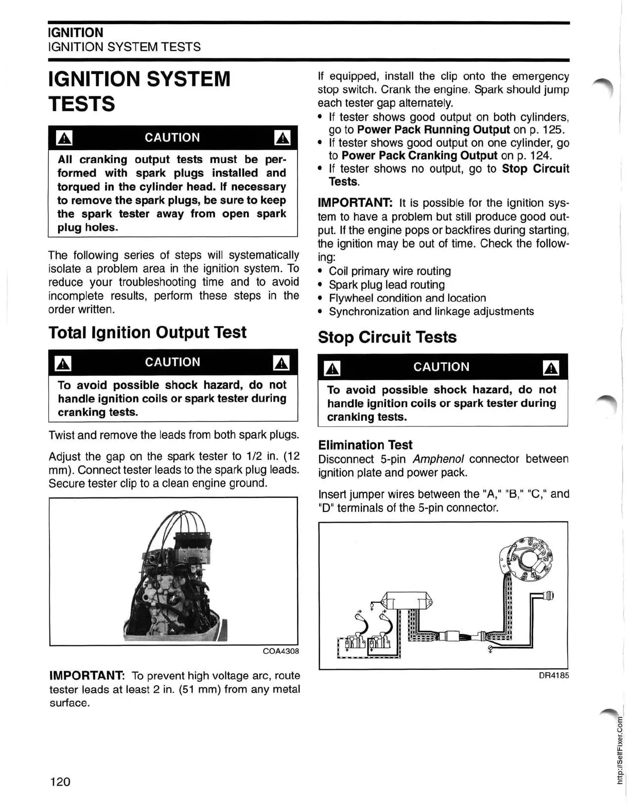
Elimination Test
Disconnect 5-
pin
Amphenol connector between
ignition
plate and power pack.
Insert jumper wires between the "A," "B,"
"C
," and
"0" terminals of the 5-pin connector.
DR4185
 Loading...