POWERHEAD
INSPECTION
INSPECTION
All Models
Before any inspection process can begin, all inter-
nal components must
be
clean and free of excess
oil. Refer to CLEANING
on
p.
193.
Make a
visual inspection of all internal compo-
nents. Check for
unusual wear patterns, scuffing
or deterioration of
aluminum parts, heat-related
discoloration
of bearings or bearing surfaces, and
broken components.
Use a micrometer to measure the diameter of
each crankpin and main bearing
journal. Measure
the
lower main bearing journal if the bearing was
removed. Refer to
TECHNICAL DATA
on
p.
30
for
dimensions.
Check for
cylinder head warpage using a piece of
bar stock or machinist's straightedge and a
feeler
gauge set.
• Cylinder head warpage must not exceed 0.004
in
. (0.10 mm) per inch ot measurement.
Replace head it warpage exceeds this dimen-
sion.
Use
Cylinder Bore Gauge,
PIN
771310, to inspect
each
cylinder bore for
an
out-ot-round, oversize,
or tapered condition. Make sure the gauge or
micrometer
is
perfectly square
in
the bore when
measuring.
194
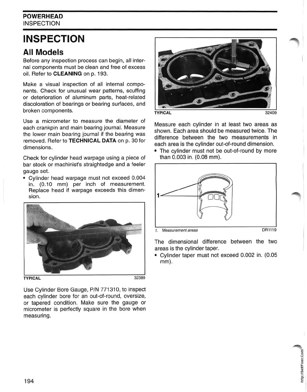
Measure each cylinder
in
at least two areas as
shown. Each area
should
be
measured twice. The
difference between the two measurements
in
each area
is
the cylinder out-ot-round dimension.
• The cylinder must not
be
out-ot-round by more
than
0.003
in.
(0.08 mm).
1....:::;.....------i
'r-W'"
1.
Measurement areas
DR1119
The dimensional difference between the two
areas
is
the cylinder taper.
• Cylinder taper must not exceed 0.002
in.
(0.05
mm).
'E
o
U
Qj
)(
~
Qj
~
~
I
 Loading...