Disassembly
9.9/15 MODELS
IMPORTANT: Changing original factory fuel
mixture calibrations beyond the limits allowed by
the tamper resistant device
is
a violation of federal
law.
Changes to the original design or adjustment
limits become the responsibilty of the servicing
technician and/or the owner. The
following proce-
dures must
be
followed EXACTLY to ensure com-
pliance with emissions standards.
IMPORTANT: This carburetor uses a tamper
resistant
low speed needle and body cover
assembly (except 10HR models). The needle
valve
is
NOT removable from the cover and
is
adjustable within a limited range. If the needle
is
turned for any reason, it should be returned to
its
original location.
HR Models Only
Remove the low-speed needle and spring from
the carburetor body cover.
All Models
Remove the six cover screws. Lift the cover and
FUEL
SYSTEM
CARBURETOR
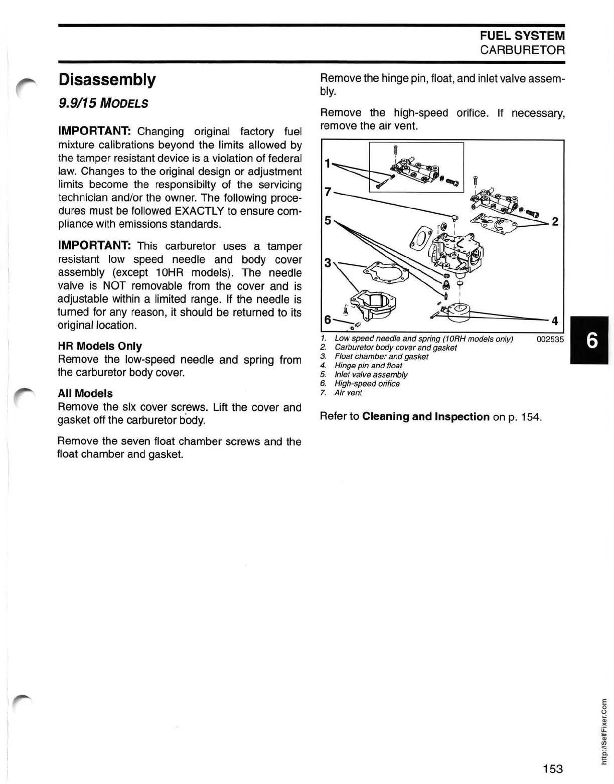
Remove the hinge pin, float, and inlet valve assem-
bly.
Remove the high-speed orifice.
If
necessary,
remove the air vent.
1. Low speed needle and spring (10RH models only)
2. Carburetor body cover and gasket
3.
Float chamber and gasket
4. Hinge pin and float
41
002535
5. Inlet valve assembly
6.
High-speed orifice
7.
Air
vent
gasket off the carburetor
b·ody.
Refer to Cleaning and Inspection
on
p. 154.
Remove the seven
float chamber screws and the
float chamber and gasket.
153
E
o
U
Qj
)(
~
Qj
~
ii
E
 Loading...