9.9/15 Models
The difference between your measurements and
standard bore dimension is
cylinder oversize.
Refer to
TECHNICAL
DATA
on
p.
30 for dimen-
sions.
• The cylinder must not be oversize by more than
0.002 in. (0.05 mm).
IMPORTANT: If any cylinder is outside these tol-
erances, it must be bored oversize. One oversize
piston
is
available for this engine 0.020 in. (0.508
mm).
To
determine oversize bore, add 0.020 in.
(0.508 mm) to the standard bore. Refer to TECH-
NICAL DATA
on
p.
30. It is permissible to have
one or more oversize pistons
in
an engine.
Measure the piston
in
two locations, 90
0
apart
from each other, 1/8 in. (3 mm) above the bottom
of
the piston skirt.
• The difference between the two measurements
is the out-of-roundness and must be no more
than
0.002
in.
(0.05 mm).
)
)
~'"
0
...
____
L
__
LiIIIIIII
t
C03082
Place each ring, separately,
in
its respective bore.
Use a piston to square the ring in the
cylinder. Use
a
feeler gauge to measure the ring end gap. The
ring gap must be within
0.005 to 0.015 in. (0.13 to
0.38 mm).
32408
POWERHEAD
INSPECTION
Use a feeler gauge to check groove side clear-
ance on the lower square rings. Install each
square ring on its piston. With the ring seated in its
groove, make
several checks around the piston.
The side
clearance must not exceed 0.004 in.
(0.10 mm).
32407
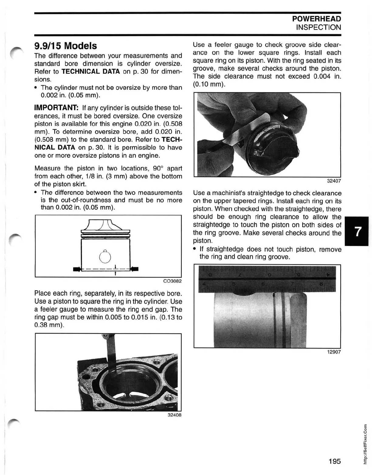
Use a machinist's straightedge to check clearance
on the upper tapered rings. Install each ring on its
piston. When checked with the straightedge, there
should be enough ring clearance to allow the •
straightedge to touch the piston on both sides of
the ring groove. Make
several checks around the
piston.
• If straightedge does not touch piston, remove
the ring and
clean ring groove.
12907
195
 Loading...