Ensure that you have the following parts and tools available:
•
DC power source cables (12–14 AWG) with ring lug (Molex 190700067 or equivalent)
(not provided)
•
Phillips (+) screwdriver, number 2
To connect DC power to the switch:
1. Ensure that the power supplies are fully inserted in the chassis and the screws on their
faceplates are tightened.
2. Ensure that the input circuit breaker is open so that the voltage across the DC power
source cable leads is 0 V and that the cable leads will not become active while you
are connecting DC power.
NOTE: The DC power supply in the switch has four terminals labeled A+,
B+, A–, and B– (see Figure 43 on page152) for connectingDC power source
cables labeled positive (+) and negative (–). The DC power supplies are
shipped with jumpers from A+ input toB+ input tied together and jumpers
from A– input to B– input tied together.
NOTE: The A+ and B+ terminals are referred to as +RTN and A– and B–
terminals arereferredtoas–48 V in“DC Power Wiring Sequence Warning”
on page 281 and “DC Power Electrical Safety Guidelines for Switches” on
page 276.
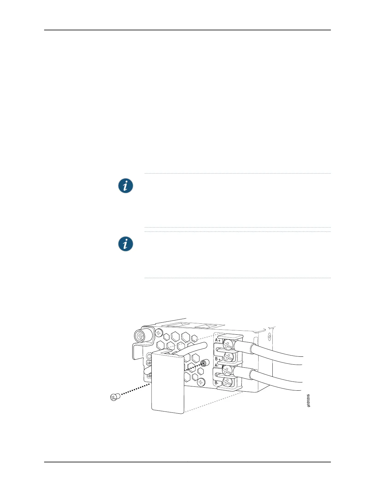
3. Removethe screw securing the terminal blockcover using the screwdriver and remove
the terminal block cover (see Figure 44 on page 153). Save the screw.
Figure 44: Removing the Terminal Block Cover from a DC Power Supply
4. Remove the screws on the terminals using the screwdriver. Save the screws.
153Copyright © 2017, Juniper Networks, Inc.
Chapter 13: Connecting the Switch to Power
 Loading...


