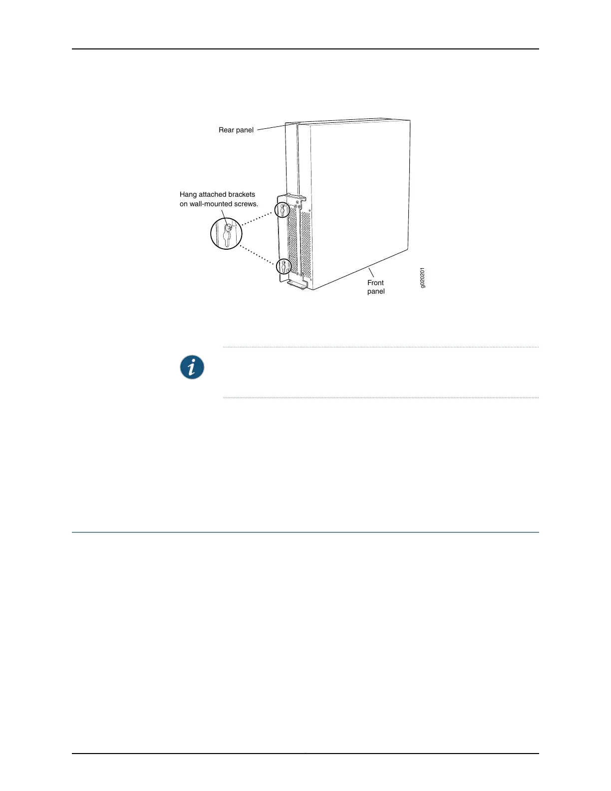
Figure 38: Mounting the Switch on a Wall
Hang attached brackets
on wall-mounted screws.
g020201
Front
panel
Rear panel
5. Tighten the mounting screws.
NOTE: If it is an EX4200-24F switch, we recommend you insert dust covers
in unused SFP ports.
Related
Documentation
Connecting AC Power to an EX4200 Switch on page 149•
• Connecting DC Power to an EX4200 Switch on page 152
• Connecting and Configuring an EX Series Switch (CLI Procedure) on page 165
• Connecting and Configuring an EX Series Switch (J-Web Procedure) on page 168
• Wall-Mounting Warning for EX4200 Switches on page 258
Installing and Removing EX4200 Switch Hardware Components
The EX4200 switch chassis is a rigid sheet-metal structure that houses the hardware
components. The field-replaceable units (FRUs) in EX4200 switches are:
•
Power supply
•
Fan tray
•
Uplink module
•
Transceivers
The power supply, fan tray, uplink module, and transceivers are hot-removable and
hot-insertable: You can remove and replace them without powering off the switch or
disrupting switch functions.
Copyright © 2017, Juniper Networks, Inc.140
EX4200 Switch Hardware Guide
 Loading...


