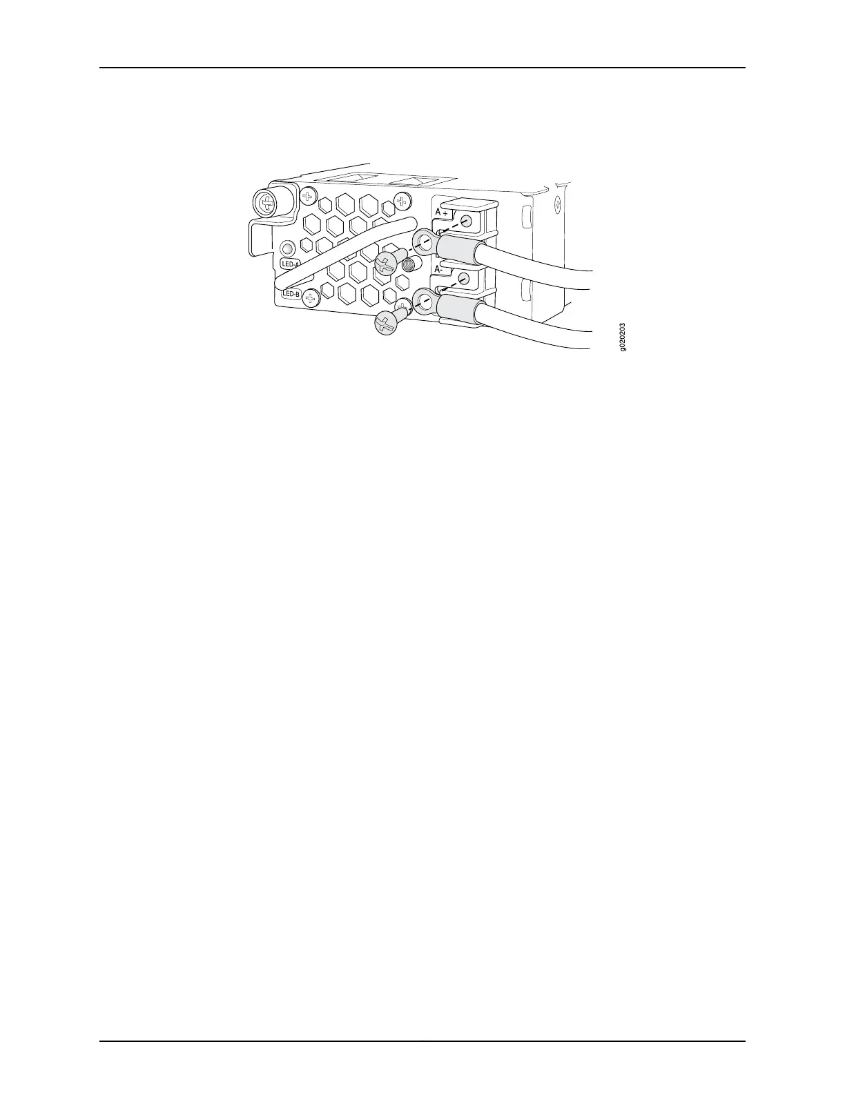
Figure 45: Securing Ring Lugs to the Terminals on the DC Power Supply
6. Replace the terminal block cover and secure it using the screw. Use the screwdriver
to tighten the screw.
7. Close the input circuit breaker.
8. Verify that the LEDs on the power supply are lit green and are on steadily.
Related
Documentation
• Connecting and Configuring an EX Series Switch (CLI Procedure) on page 165
• Connecting and Configuring an EX Series Switch (J-Web Procedure) on page 168
• Power Supply in EX4200 Switches on page 33
• DC Power Supply LEDs in EX4200 Switches on page 38
155Copyright © 2017, Juniper Networks, Inc.
Chapter 13: Connecting the Switch to Power
 Loading...


