• Removing a Fan Tray from an EX4200 Switch on page 180
• Installing an Uplink Module in an EX4200 Switch on page 187
• Removing an Uplink Module from an EX4200 Switch on page 189
• Installing a Transceiver on page 193
• Removing a Transceiver on page 195
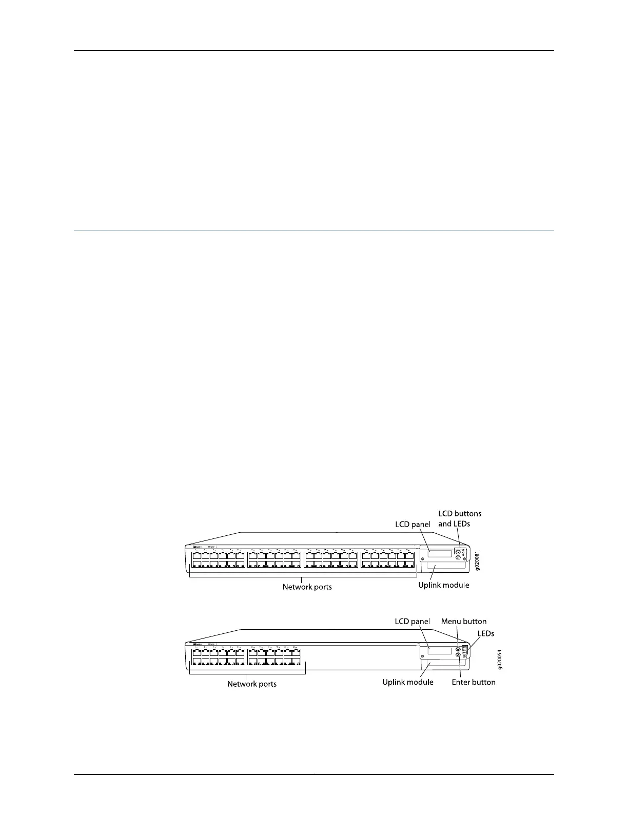
Front Panel of an EX4200 Switch
The front panel of an EX4200 switch consists of the following components:
•
Network ports—depending on the switch model, either:
•
10/100/1000Base-T Gigabit Ethernet ports, some or all of which are enabled for
Power over Ethernet (PoE)
•
100Base-FX/1000Base-X SFP ports for use with fiber-optic connections
•
Uplink module ports—SFP, SFP+, or XFP ports (Installing the uplink module is an
optional.)
•
LCD panel and the LCD navigation buttons
•
Chassis status LEDs
•
Network port LEDs
Figure 1 on page 11 shows the front panel of an EX4200 switch with 48 Gigabit Ethernet
ports. Figure 2 on page 11 shows the front panel of an EX4200 switch with 24 Gigabit
Ethernet ports. Figure 3 on page 12 shows the front panel of an EX4200-24F switch with
24 SFP ports for use with fiber-optic connectors.
Figure 1: EX4200 Switch with 48 Gigabit Ethernet Ports
Figure 2: EX4200 Switch with 24 Gigabit Ethernet Ports
11Copyright © 2017, Juniper Networks, Inc.
Chapter 2: Chassis Components and Descriptions
 Loading...


