There are two classes of alarm messages:
•
Chassis alarms—Indicate a problem with a chassis component such as the cooling
system or power supplies.
•
Interface alarms—Indicate a problem with a specific network interface.
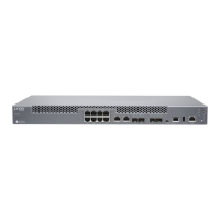
Front Panel LEDs
The front panel on the router contains LEDs and buttons that allow you to troubleshoot
the router.
LEDs on the front panel include the following:
•
Alarm LEDs—Two LEDs located on the left side of the front panel indicate critical and
warning alarms on the router. The circular LED lights red to indicate a critical condition
that can result in a system shutdown. The triangular LED lights yellow to indicate a
less severe condition that requires monitoring or maintenance.
•
System LED—One LED on the left side of the front panel indicates the status of the
router. The LED is located below the SYS OK label. The LED lights steadily green when
the router is functioning normally and blinks green when the router is transitioning
online.
•
Routing Engine LED—One bicolor LED on the left side of the front panel indicates the
status of the Routing Engine. The LED is located below the RE label. The LED is lit
steadily green when the Routing Engine is functioning normally and is lit red when the
Routing Engine has failed.
•
Link LEDs—Four LEDs, labeled LINK, indicate the status of the ports for the fixed
10-Gigabit Ethernet MIC. The LED is green when the link is up, and is off when there is
no link. The LINK LEDs are located to the right of the port on the front panel.
Component LEDs
The following LEDs are located on various router components and display the status of
those components:
•
MIC LEDs—One LED, labeled OK/FAIL, on each MIC faceplate indicates the MIC’s status.
For more information, see the MX Series Interface Module Reference. On the fixed MX80
router, each RJ-45 port has an additional link LED. The LED is green when the link is up
and is off when there is no link.
•
Power supply LEDs—One bicolor LED, on each power supply faceplate indicates the
status of that power supply. The LED is lit blue when the power supply is functioning
normally and is blinking red when the power supply has failed.
See Also ping•
• traceroute
• show chassis alarms
Copyright © 2019, Juniper Networks, Inc.128
MX5, MX10, MX40, and MX80 Universal Routing Platforms Hardware Guide

 Loading...