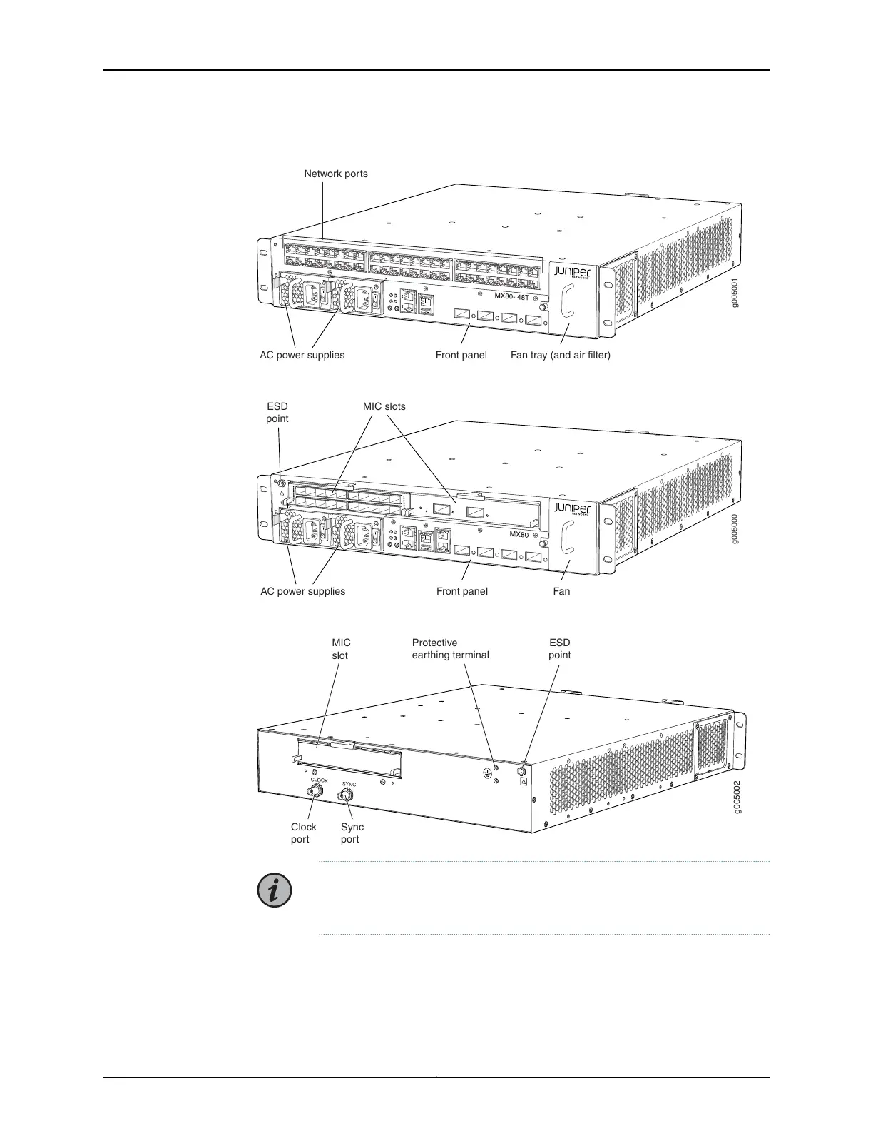
Figure 8: Front View of the MX80 Router (Fixed Chassis)
g005001
Front panel Fan tray (and air filter)AC power supplies
Network ports
Figure 9: Front View of the MX80 Router (Modular Chassis)
g005000
Front panel Fan
MIC slots
AC power supplies
ESD
point
Figure 10: Rear View of the MX5, MX10, MX40, and MX80 Routers
g005002
CLOCK
SYNC
Clock
port
MIC
slot
Sync
port
ESD
point
Protective
earthing terminal
NOTE: The port labeled CLOCK provides 10 Mhz output. The port labeled
SYNC provides 1 PPS output.
MX5, MX10, MX40, and MX80 Baseboard Description
The baseboard is located in the center of the chassis and forms the rear of the MIC card
cage. The baseboard is not replaceable. The MICs and power supplies install into the
Copyright © 2019, Juniper Networks, Inc.26
MX5, MX10, MX40, and MX80 Universal Routing Platforms Hardware Guide

 Loading...