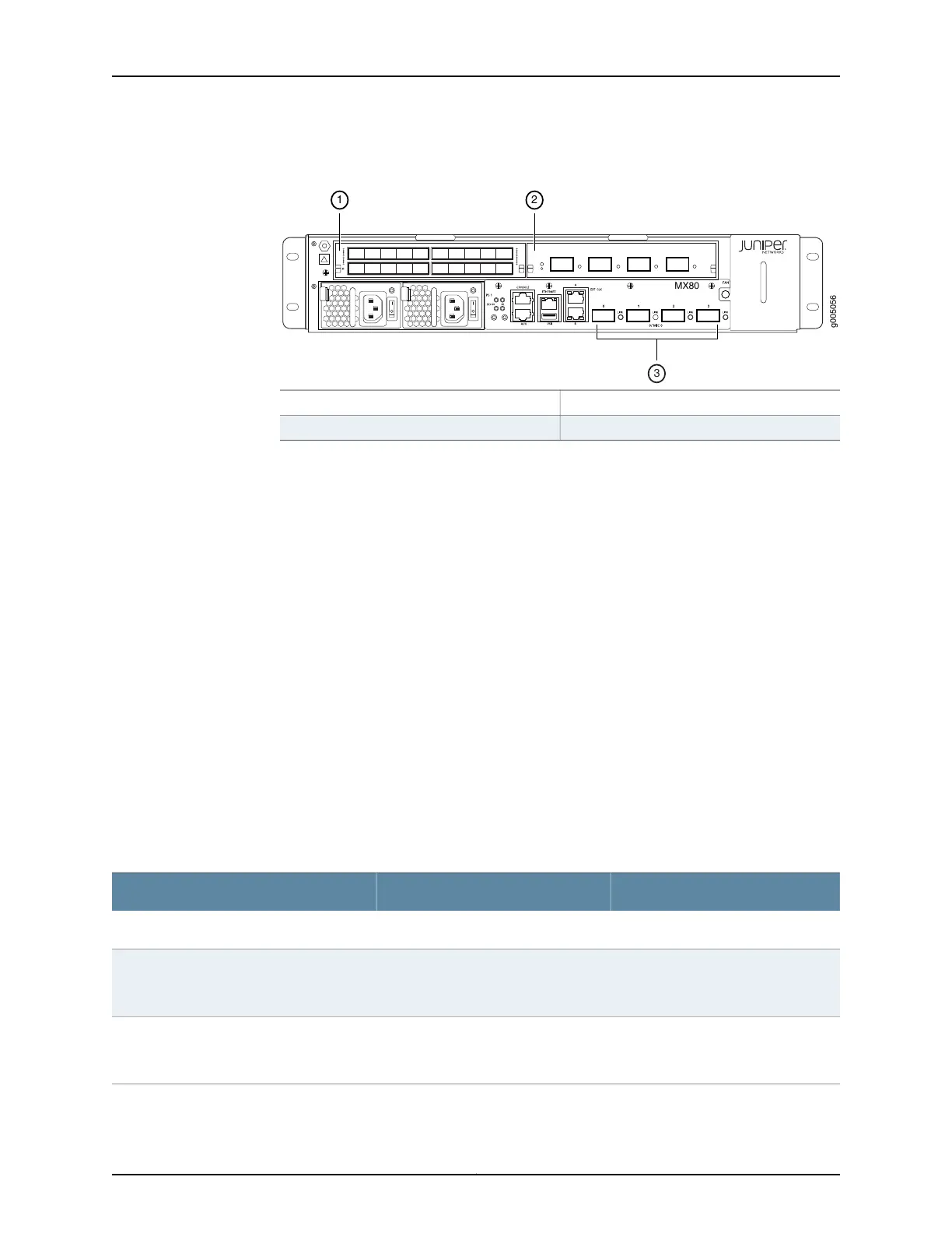
Figure 21: MX5, MX10, MX40, and MX80 Interface Port Mapping
3—1— 10-Gigabit Ethernet ports (FPC 0, PIC 0)MIC slot 1/0 (FPC 1, PIC 0 and PIC 1)
2—MIC slot 1/1 (FPC 1, PIC 2 and PIC 3)
The chassis has two built-in MPCs, which are represented in the CLI as FPC 0 and FPC 1.
MPC 0 (FPC 0) contains a 4-port 10-Gigabit Ethernet MIC. Both the MPC and the MIC
are considered fixed and are built into the front of the chassis. The MIC is represented as
MIC 0 in the CLI and is logically divided into a single PIC, which is represented as PIC 0.
MPC 1 (FPC 1) has two slots, which accept up to two MICs. The MICs are represented as
MIC 0 and MIC 1 in the CLI and are logically divided into PICs depending on their type. A
MIC installed in MIC slot 1/0 is represented in the CLI as PIC 0 and PIC 1. A MIC installed
in MIC slot 1/1 is represented as PIC 2 and PIC 3.
MX80 series routers also contain a MIC slot in the rear of the chassis that supports the
optional Juniper Networks Multiservices MIC. The Multiservices MIC installed in the rear
MIC slot is represented in the CLI as FPC 0, MIC 1, and PIC 2. The port number for the rear
slot in the MX80 chassis is 0.
The port numbers on the MICs correspond to the port numbers in the interface. See the
MX Series Interface Module Reference for more information on specific MICs.
Table 29 on page 55 summarizes the relationship between the components and the
interface names.
Table 29: MX5, MX10, MX40, and MX80 Components and Their Interface Names
Interface NamesName in the CLIComponent
xe-0/0/0 through xe-0/0/34x 10GE XFPBuilt-in 4-port 10-Gigabit Ethernet MIC
type-1/0/port
type-1/1/port
See MX Series Interface Module
Reference.
MIC installed in MIC slot 1/0
type-1/2/port
type-1/3/port
See MX Series Interface Module
Reference.
MIC installed in MIC slot 1/1
55Copyright © 2019, Juniper Networks, Inc.
Chapter 1: Overview

 Loading...