2. Plug the RJ-45 end of the serial cable (Figure 37 on page 92 shows the connector)
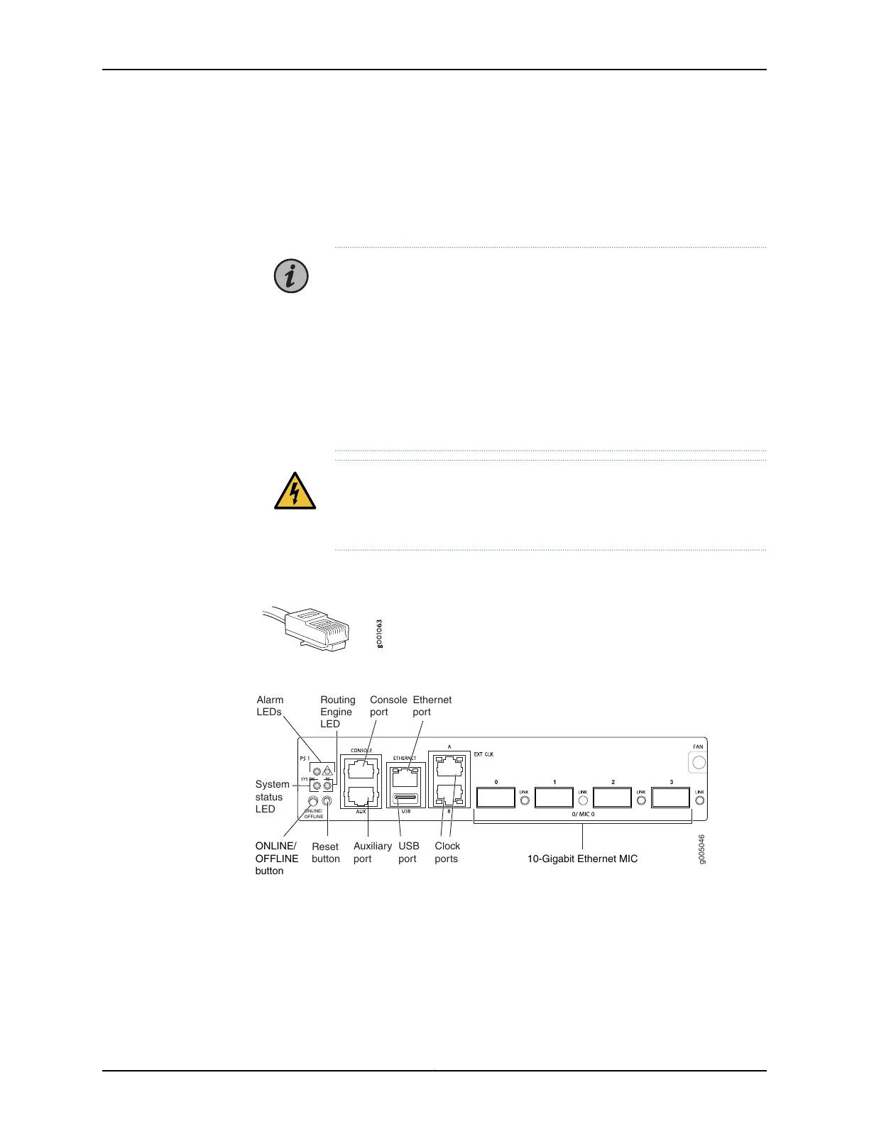
into the AUX port or CONSOLE port on the front panel. Figure 38 on page 92 shows
the ports.
3. Plug the female DB-9 end into the device's serial port.
NOTE:
For console devices, configure the serial port to the following values:
•
Baud rate—9600
•
Parity—N
•
Data bits—8
•
Stop bits—1
•
Flow control—none
WARNING: Do not connect Power over Ethernet (PoE) enabled cables to
the console port. These cables are known to cause damage resulting in
console port failure.
Figure 37: Routing Engine Console and Auxiliary Cable Connector
Figure 38: Auxiliary and Console Ports
g005046
ONLINE/
OFFLINE
Auxiliary
port
USB
port 10-Gigabit Ethernet MIC
Console
port
Ethernet
port
Clock
ports
Routing
Engine
LED
Alarm
LEDs
System
status
LED
Reset
button
ONLINE/
OFFLINE
button
Related
Documentation
Installing the MX5, MX10, MX40, and MX80 Cable Management Bracket on page 79•
• Connecting Interface Cables to MX5, MX10, MX40, and MX80 Routers
• Initially Configuring MX5, MX10, MX40, and MX80 Routers on page 93
Copyright © 2019, Juniper Networks, Inc.92
MX5, MX10, MX40, and MX80 Universal Routing Platforms Hardware Guide

 Loading...