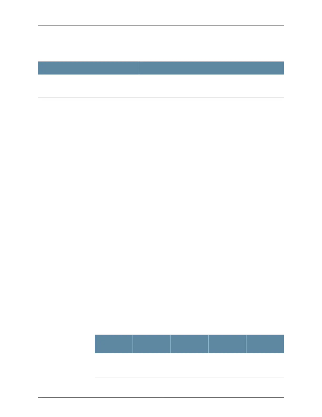
Table 37: Estimated Values for Factors Causing Link Loss (continued)
Estimated Link-Loss ValueLink-Loss Factor
Single-mode—0.5 dB/km
Multimode—1 dB/km
Fiber attenuation
The following sample calculation for a 2-km-long multimode link with a power budget
(P
B
) of 13 dB uses the estimated values from Table 37 on page 70 to calculate link loss
(LL) as the sum of fiber attenuation (2 km @ 1 dB/km, or 2 dB) and loss for five connectors
(0.5 dB per connector, or 2.5 dB) and two splices (0.5 dB per splice, or 1 dB) as well as
higher-order mode losses (0.5 dB). The power margin (P
M
) is calculated as follows:
P
M
= P
B
– LL
P
M
= 13 dB – 2 km (1 dB/km) – 5 (0.5 dB) – 2 (0.5 dB) – 0.5 dB
P
M
= 13 dB – 2 dB – 2.5 dB – 1 dB – 0.5 dB
P
M
= 7 dB
The following sample calculation for an 8-km-long single-mode link with a power budget
(P
B
) of 13 dB uses the estimated values from Table 37 on page 70 to calculate link loss
(LL) as the sum of fiber attenuation (8 km @ 0.5 dB/km, or 4 dB) and loss for seven
connectors (0.5 dB per connector, or 3.5 dB). The power margin (P
M
) is calculated as
follows:
P
M
= P
B
– LL
P
M
= 13 dB – 8 km (0.5 dB/km) – 7(0.5 dB)
P
M
= 13 dB – 4 dB – 3.5 dB
P
M
= 5.5 dB
In both examples, the calculated power margin is greater than zero, indicating that the
link has sufficient power for transmission and does not exceed the maximum receiver
input power.
Routing Engine Interface Cable Specifications for MX5, MX10, MX40, and MX80 Routers
Table 38 on page 71 lists the specifications for the cables that connect to management
ports.
Table 38: Cable Specifications for Routing Engine Management
Router
Receptacle
Maximum
Length
Cable/Wire
Supplied
Cable
SpecificationPort
RJ-45 female6 ft (1.83 m)One 6-ft
(1.83-m) length
with RJ-45/DB-9
connectors
RS-232
(EIA-232) serial
cable
Routing Engine
console or
auxiliary
interface
71Copyright © 2019, Juniper Networks, Inc.
Chapter 2: Site Planning, Preparation, and Specifications

 Loading...