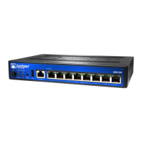
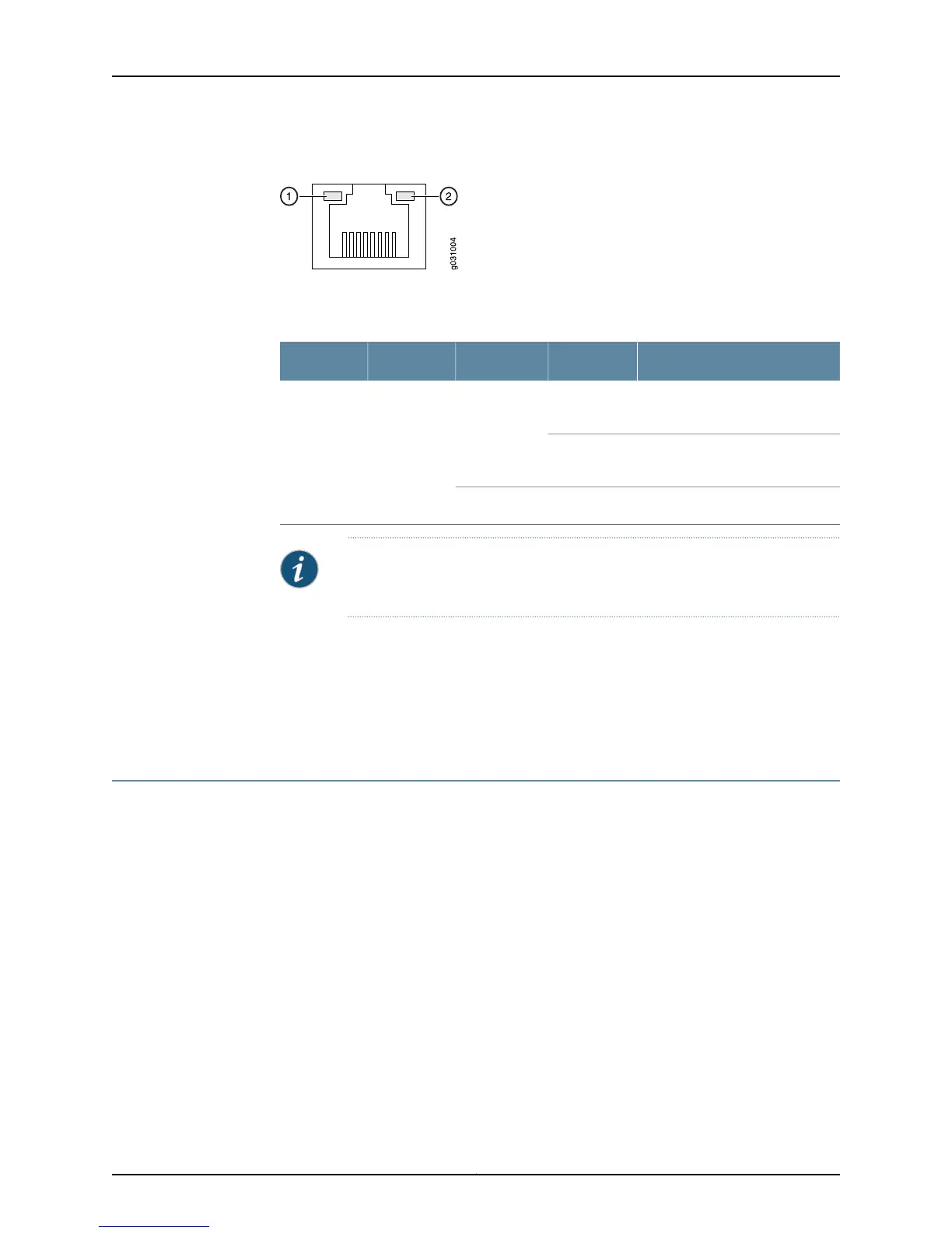
Figure 7: SRX110 Services Gateway Ethernet Port LEDs
Table 10 on page 15 describes the built-in Ethernet port LEDs.
Table 10: SRX110 Services Gateway Built-In Ethernet Port LEDs
DescriptionStateColorFunctionNumber
Link is active. Data
communication is taking place.
On, blinkingGreenLINK/ACTIVE
LED
1
Link is active. No data
communication is taking place.
On, not
blinking
Link is inactive.Off
NOTE: The LED marked as 2 in Figure 7 on page 15 is not functional in this
release.
Related
Documentation
SRX110 Services Gateway Specifications on page 7•
• SRX110 Services Gateway Front Panel and Back Panel Views with 3G and Integrated
VDSL2 on page 9
• SRX110 Services Gateway Boot Devices and Dual-Root Partitioning Scheme on page 15
SRX110 Services Gateway Boot Devices and Dual-Root Partitioning Scheme
This topic includes the following sections:
•
Boot Devices on page 15
•
Dual-Root Partitioning Scheme on page 15
Boot Devices
The SRX110 Services Gateway can boot from two devices:
•
CompactFlash (default; always present)
•
USB storage key (alternate)
Dual-Root Partitioning Scheme
Dual-root partitions allow services gateways to remain functional if the file system
becomes corrupted, and they facilitate easy recovery of the corrupted file system.
15Copyright © 2013, Juniper Networks, Inc.
Chapter 2: SRX110 Services Gateway Hardware Components and Specifications
 Loading...