8. CYLINDER HEAD/VALVES
8-2
XCITING 500
SERVICE INFORMATION
GENERAL INSTRUCTIONS
• The cylinder head can be serviced with the engine installed in the frame. Coolant in the radiator
and water jacket must be drained first.
• When assembling, apply molybdenum disulfide grease or engine oil to the valve guide movable
parts and valve arm sliding surfaces for initial lubrication.
• The valve rocker arms are lubricated by engine oil through the cylinder head engine oil passages.
Clean and unclog the oil passages before assembling the cylinder head.
• After disassembly, clean the removed parts and dry them with compressed air before inspection.
• After removal, mark and arrange the removed parts in order. When assembling, install them in
the reverse order of removal.
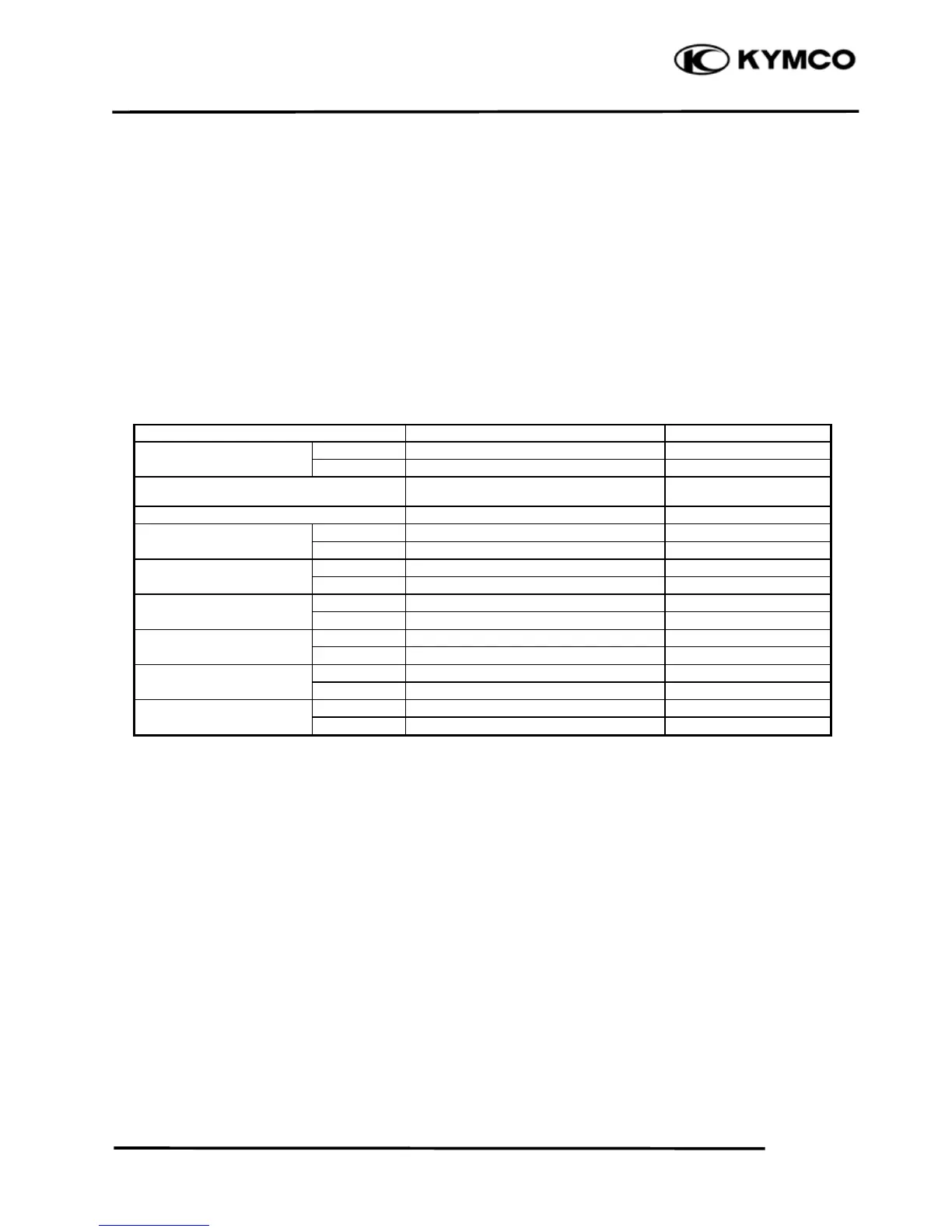
SPECIFICATIONS
Unit: mm (in)
Ite
TORQUE VALUES
Cylinder head bolt (13) 13 N•m (1.3 kgf•m, 9 lbf•ft) Apply engine oil to threads
Cylinder head bolt (1 – 4) 48 N•m (4.8 kgf•m, 35 lbf•ft) Apply engine oil to threads
Cylinder head bolt (5 – 12) 23 N•m (2.3 kgf•m, 17 lbf•ft) Apply engine oil to threads
Cylinder head cover bolt 10 N•m (1 kgf•m, 7 lbf•ft)
Cylinder head cover bolt 10 N•m (1 kgf•m, 7 lbf•ft)
Breather separator bolt 13 N•m (1.3 kgf•m, 9 lbf•ft)
Cam chain tensioner bolt 12 N•m (1.2 kgf•m, 9 lbf•ft)
Tensioner pivot bolt 10 N•m (1 kgf•m, 7 lbf•ft)
Rocker arm shaft 45 N•m (4.5 kgf•m, 32 lbf•ft)
SPECIAL TOOLS
Valve spring compressor E040
Valve clearance (cold)
Camshaft cam height
Valve rocker arm I.D.
Valve guide I.D.
Valve stem O.D.
 Loading...