Configuration
7-6
SHB9300CRV EN 2.0
Display code
Displays the current input value. Inputs with identical codes are distinguished by the subcode. The
subcode is attached to the code (Cxxxx/1). These codes are displayed via their subcodes.
Display codes cannot be processed.
Function
Represents the mathematical function as a block diagram. Fig. 7-1
Parameter setting code
Adaptation of the function or the behaviour to the application.The possible settings are explained
and shown in the text and/or the line diagram.
Output symbol
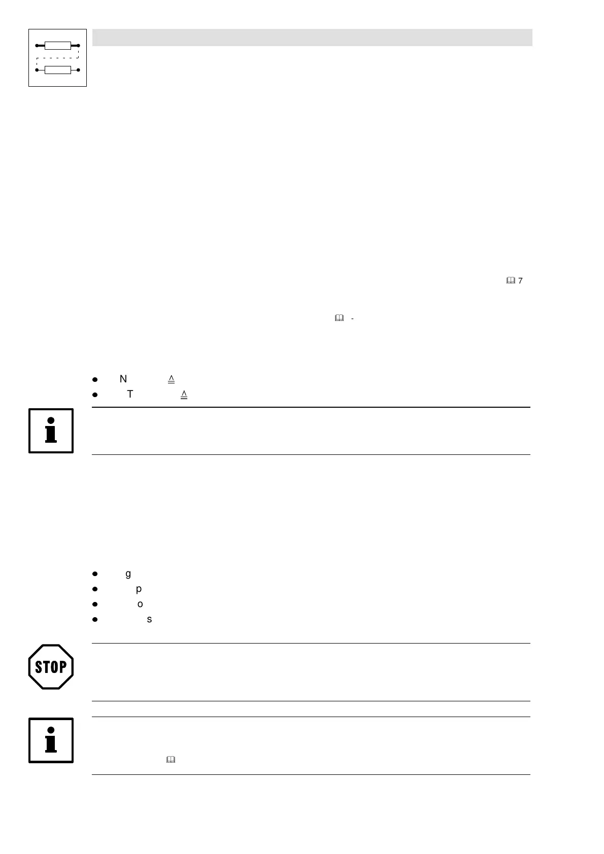
Designates the signal type. Connections with inputs of the same signal type are possible.
(
&
7-4)
Every output is defined by a selection number.The selection numbers are subdivided into selection
tables (1 ... 4) according to the different signal types.
(
&
7-323)
An output is linked to an input by the selection numbers.
Example:
(FCNT1, see Fig. 7-1)
l
FCNT1-OUT selection number 6400 (analog signal, selection list 1).
l
FCNT1-EQUAL selection number 6400 (dgitial signal, selection list 2).
Note!
Output, which are not linked, cannot be configured.
Output name
Consists of the FB name and a designation.Outputs with the same function are distinguished by a
number behind their designation.
7.3.3 Connection of function blocks
General rules
l
Assign a signal source to an input.
l
One input can have only one signal source.
l
Inputs of different function blocks can have the same signal source.
l
Only the same types of signals can be connected. Thus, the analog output signal of one
function block can only be connected to the analog input of the other function block.
Stop!
Existing connections, which are not desired, must be removed by reconfiguration. Otherwise, the
drive cannot perform the desired function.
Note!
Lenze offers a net-list generator for the visualization of existing connections (see accessories: PC
program GDC).
(
&
13-4)
 Loading...