EasyManua.ls Logo

Lenze EVS9326-EK User Manual

Lenze EVS9326-EK
524 pages
To Next Page IconTo Next Page
To Previous Page IconTo Previous Page
Page #359 background imageLoading...
Page #359 background image
Function block library
7-242

SHB9300CRV EN 2.0
Synchronized stretching/compression of drive motion
Note!
This function is only valid for the cam drive, not for the master drive!
Synchronized stretching and compression is required for the following:
l
If master value and cam drive must run absolutely synchronously.
l
The factor must be changed during operation.
This function should be used if more than 8 profiles are required to change the cam drive travel.
The travel can be changed on-line via stretching and compression.
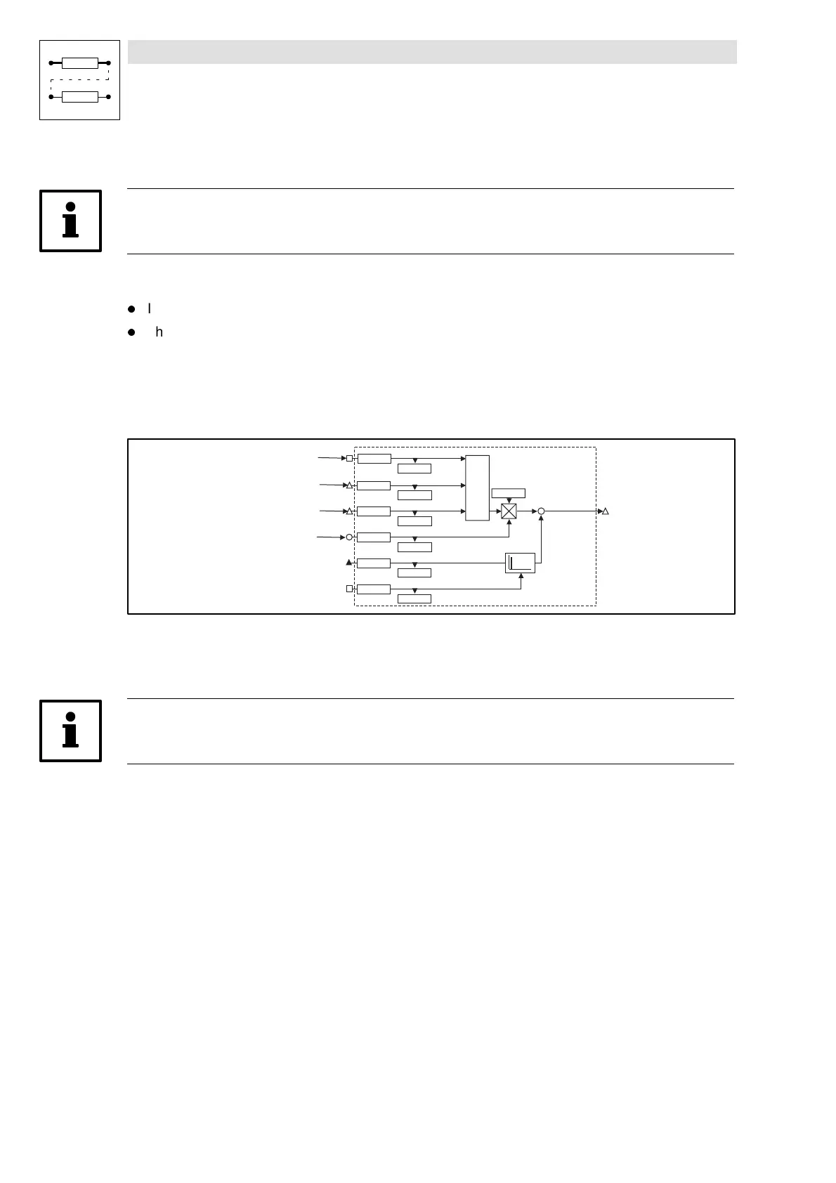
– Interconnection of function blocks
YSET1
YSET1-O UT
C 1357/1
YSET1-O FFS
C 1356/1
C 1353/1
YSET1-FACT
C 1352/1
C 1359/1
YSET1-IN
C 1358/1
+
C 1350
C 1355/1
YSET1-RESET
C 1354/1
C 1359/2
YSET1-IN-SYNCH
C 1358/2
CTRL
C 1355/2
YSET1-SYNCH
C 1354/2
CDATA-X0
CDATA-SYNCH
CDATA-NOUT
– Activate function
The function is only active if C1317 = 1.
The changeover is carried out during zero crossing of the profile.
Note!
Stretching/compression in X direction can be carried out via the input CDATA-XFACT.
7.6.79.2 Offset
It is possible to the X position by a constant value via input YSET-OFFS.
7.6.79.3 Direction reversal
There are two possibilities to inverse the direction of rotation:
1. Via code C1351/1.
2. Application of a stretching/compression factor
YSET-FACT = -100% (see also table above).
Show/Hide Bookmarks

Table of Contents

Question and Answer IconNeed help?

Do you have a question about the Lenze EVS9326-EK and is the answer not in the manual?

Lenze EVS9326-EK Specifications

General IconGeneral
BrandLenze
ModelEVS9326-EK
CategoryDC Drives
LanguageEnglish

Summary

Safety information

Technical data

Rated data

Provides detailed electrical and mechanical specifications for various product types.

Fuses and cable cross-sections

Specifies recommended fuse types and cable cross-sections for mains and motor connections.

Installation

Mechanical installation

Covers important notes on mounting, ensuring free space, and possible mounting positions for the controller.

Electrical installation

Details protection of persons, controller, motor, mains types, and cable specifications.

Power connections

Explains preparations for power connections, including mains and motor connections.

Control connections

Outlines control cable specifications, terminal assignments, and connection diagrams.

Commissioning

Before switching on

Essential checks before initial switch-on, including wiring, power connections, and motor connection.

Parameter set generation

Systematic procedure for generating a parameter set by adapting controller to mains, motor, and machine parameters.

During operation

Configuration

Working with function blocks

Guides on configuring signal flow by connecting function blocks and understanding signal types.

Monitoring

Covers various monitoring functions that protect the drive from impermissible operating conditions and their reactions.

Parameter setting

Explains how to adapt the drive to applications by setting parameters via PC or keypad.

Troubleshooting and fault elimination

Troubleshooting

Explains how operational faults are indicated via display elements or status information and lists common causes.

Fault messages

Lists fault messages, their causes, and corresponding remedies for troubleshooting.

Signal flow charts

Related product manuals