Configuration
7-245
SHB9300CRV EN 2.0
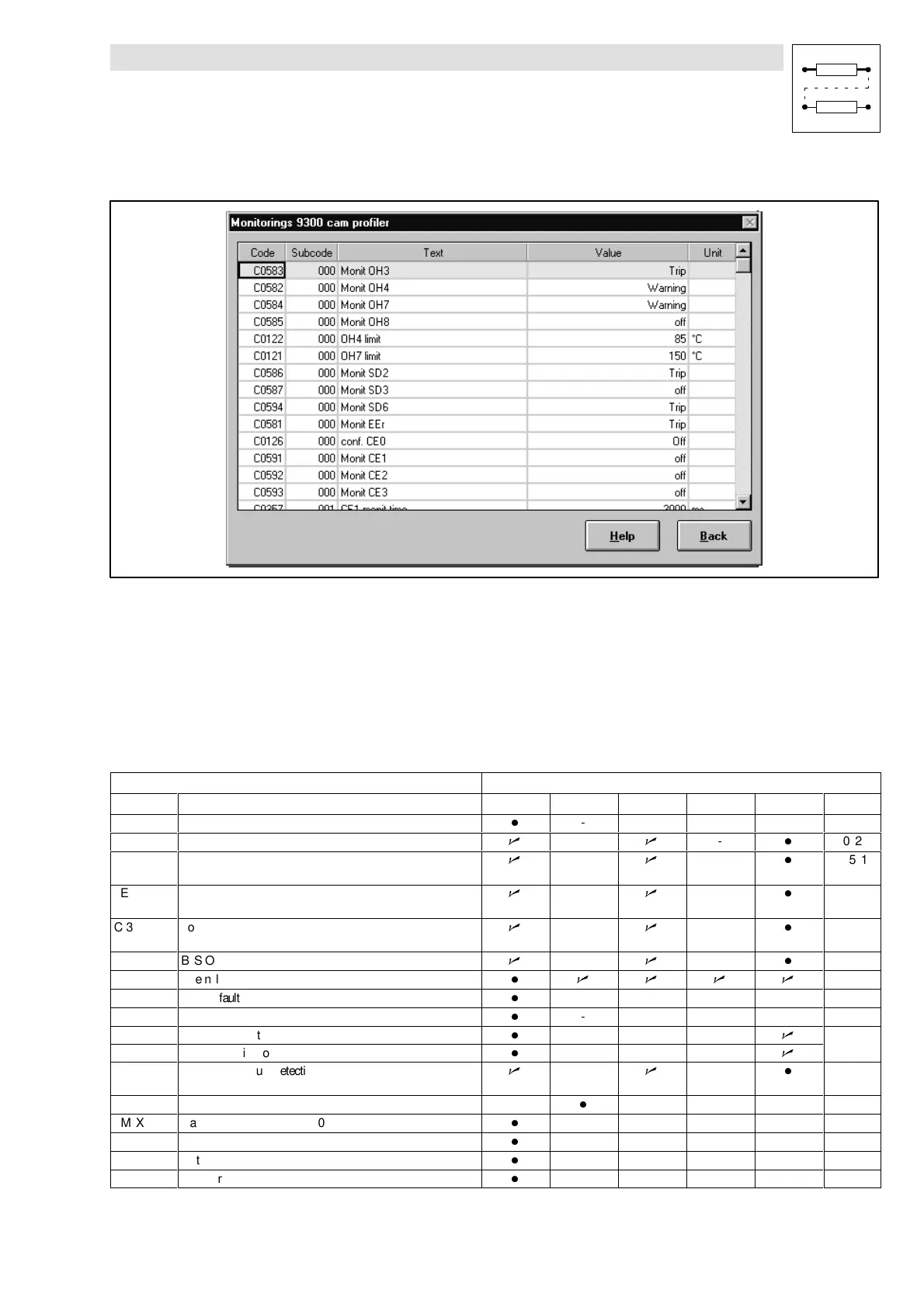
3. Click the button ”Monitorings...”.
Fig. 7-192 Dialog box ”Monitoring configuration 93xx”
4. Click the desired monitoring function.
5. Confirm possible and allowed reactions with ”OK”.
The following chapter gives an overview of all monitoring functions and their settings.
7.7.3 Monitoring functions
Overview of the fault sources detected by the controller, and the corresponding reactions
Fault message Possible reactions
Display Meaning T M W Q off Code
CCr System fault
-
- - - - -
CE0 Communication error (AIF)
T
-
T
-
-
C0126
CE1 Communication error at the process data input object CAN-IN1
(time monitoring can be set under C0357/1)
T
-
T
-
-
C0591
CE2 Communication error at the process data input object CAN-IN2
(time monitoring can be set under C0357/2)
T
-
T
-
-
C0592
CE3 Communication error at the process data input object CAN-IN3
(time monitoring can be set under C0357/3)
T
-
T
-
-
C0593
CE4 BUS-OFF state (many communication errors occurred)
T
-
T
-
-
C0595
EEr External monitoring
- T T T T
C0581
H05 Internal fault
-
- - - - -
H07 Internal fault
-
- - - - -
H10 Sensor fault heat sink temperature
-
- - -
T
C0588
H11 Sensor fault: indoor temperature
-
- - -
T
LP1 Motor phase failure detection (function block must be entered
in C0465)
T
-
T
-
-
C0597
LU Undervoltage -
-
- - - -
NMAX Maximum speed exceeded (C0596)
-
- - - - -
OC1 Short circuit
-
- - - - -
OC2 Earth fault
-
- - - - -
OC5 Ixtoverload
-
- - - - -
 Loading...