EasyManua.ls Logo

Lenze EVS9326-EK User Manual

Lenze EVS9326-EK
524 pages
To Next Page IconTo Next Page
To Previous Page IconTo Previous Page
Page #302 background imageLoading...
Page #302 background image
Function block library
7-185

SHB9300CRV EN 2.0
C 1157
PHINT3
PHINT3-O UT
PHINT3-IN
C 1158
PHINT3-LO AD
C 1153
C 1154
PHIN T3-STATUS
C 1150
C 1151
C 1159
PHINT3-SET
C 1155
Fig. 7-150 Phase inte grator (PHINT3)
S ignal
Source Note
Name Type DIS DIS format CFG List
PHINT3-IN phd C1157 dec [rpm] C1153 4 1 revolution = 65536 increments
PHINT3-LOAD d C1158 bin C1154 2 HIGH = sets the phase integrator to the input signal of
PHINT3-IN and PHINT3-STATUS = LOW
PHINT3-SET ph C1159 dec [inc] C1155 3
PHINT3-OUT ph - - - - 65536 inc = 1 encoder revolution, overflow is possible
PHINT3-STATUS d - - - - HIGH = overflow completed or distance covered
Function
l
Constant input value (PHINT1 and PHINT2)
l
Constant input value (PHINT3)
l
Input value with change of the sign (PHINT3)
l
Scaling of PHINTx-OUT
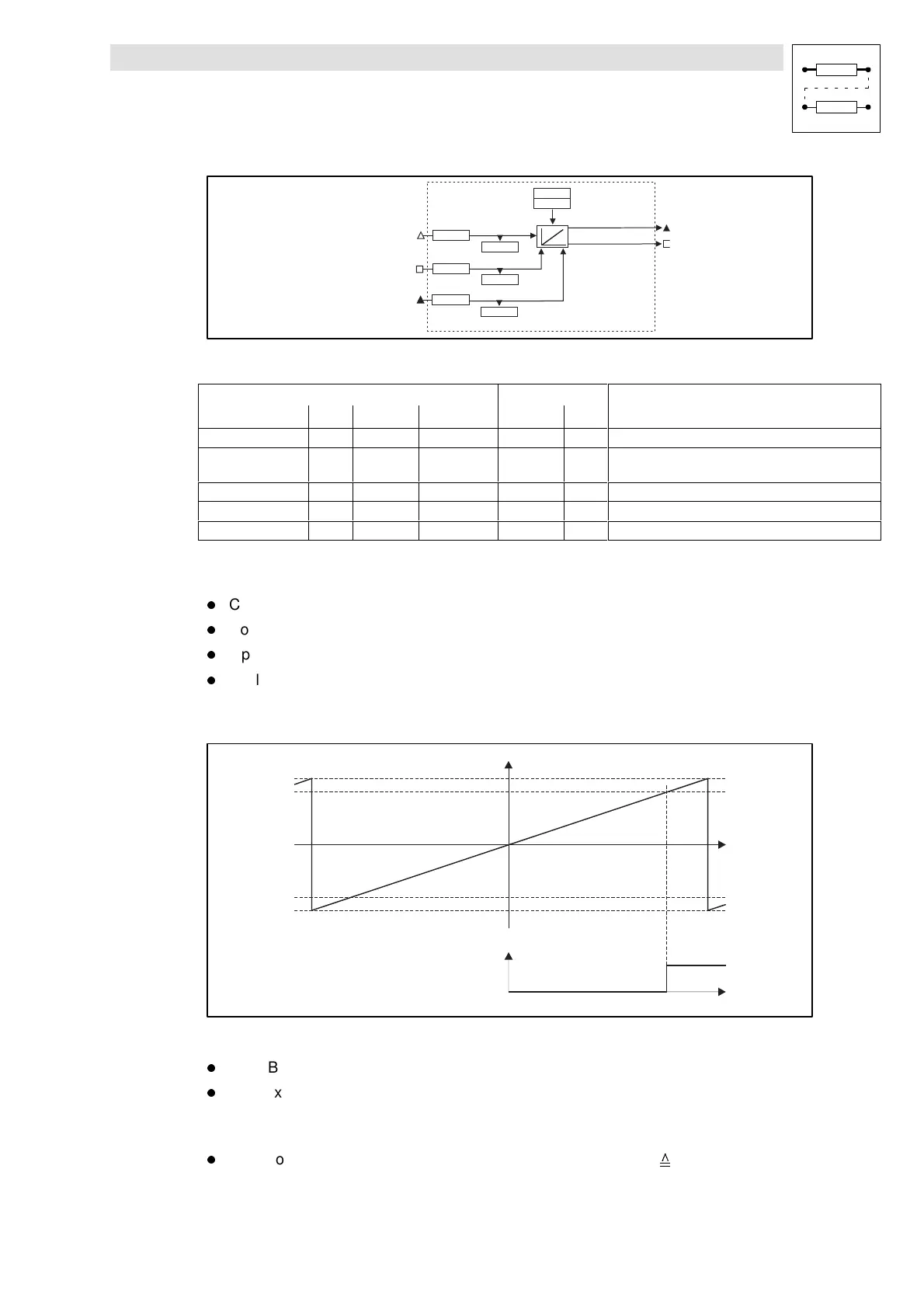
7.6.60.1 Constant input value (PHINT1 and PHINT2)
PHINTx-OUT
t
-32767 Umdr.
-C32000
+32000
+32767 Umdr.
PHINTx-FAIL
t
Fig. 7-151 Function of PHINTx with constant input value
l
The FB integrates speed or velocity values at PHINTx-IN to a phase (distance).
l
PHINTx-OUT outputs the count of the bipolar integrator.
– A positive value at PHINTx-IN increments the integrator (count is increased).
– A negative value at PHINTx-IN decrements the integrator (count is reduced).
l
If the count exceeds the value of +32767 encoder revolutions ( +2147483647 inc)
– an overflow results. The counting is continued at the value -32768.
Show/Hide Bookmarks

Table of Contents

Question and Answer IconNeed help?

Do you have a question about the Lenze EVS9326-EK and is the answer not in the manual?

Lenze EVS9326-EK Specifications

General IconGeneral
BrandLenze
ModelEVS9326-EK
CategoryDC Drives
LanguageEnglish

Summary

Safety information

Technical data

Rated data

Provides detailed electrical and mechanical specifications for various product types.

Fuses and cable cross-sections

Specifies recommended fuse types and cable cross-sections for mains and motor connections.

Installation

Mechanical installation

Covers important notes on mounting, ensuring free space, and possible mounting positions for the controller.

Electrical installation

Details protection of persons, controller, motor, mains types, and cable specifications.

Power connections

Explains preparations for power connections, including mains and motor connections.

Control connections

Outlines control cable specifications, terminal assignments, and connection diagrams.

Commissioning

Before switching on

Essential checks before initial switch-on, including wiring, power connections, and motor connection.

Parameter set generation

Systematic procedure for generating a parameter set by adapting controller to mains, motor, and machine parameters.

During operation

Configuration

Working with function blocks

Guides on configuring signal flow by connecting function blocks and understanding signal types.

Monitoring

Covers various monitoring functions that protect the drive from impermissible operating conditions and their reactions.

Parameter setting

Explains how to adapt the drive to applications by setting parameters via PC or keypad.

Troubleshooting and fault elimination

Troubleshooting

Explains how operational faults are indicated via display elements or status information and lists common causes.

Fault messages

Lists fault messages, their causes, and corresponding remedies for troubleshooting.

Signal flow charts

Related product manuals