Function block library
7-122
SHB9300CRV EN 2.0
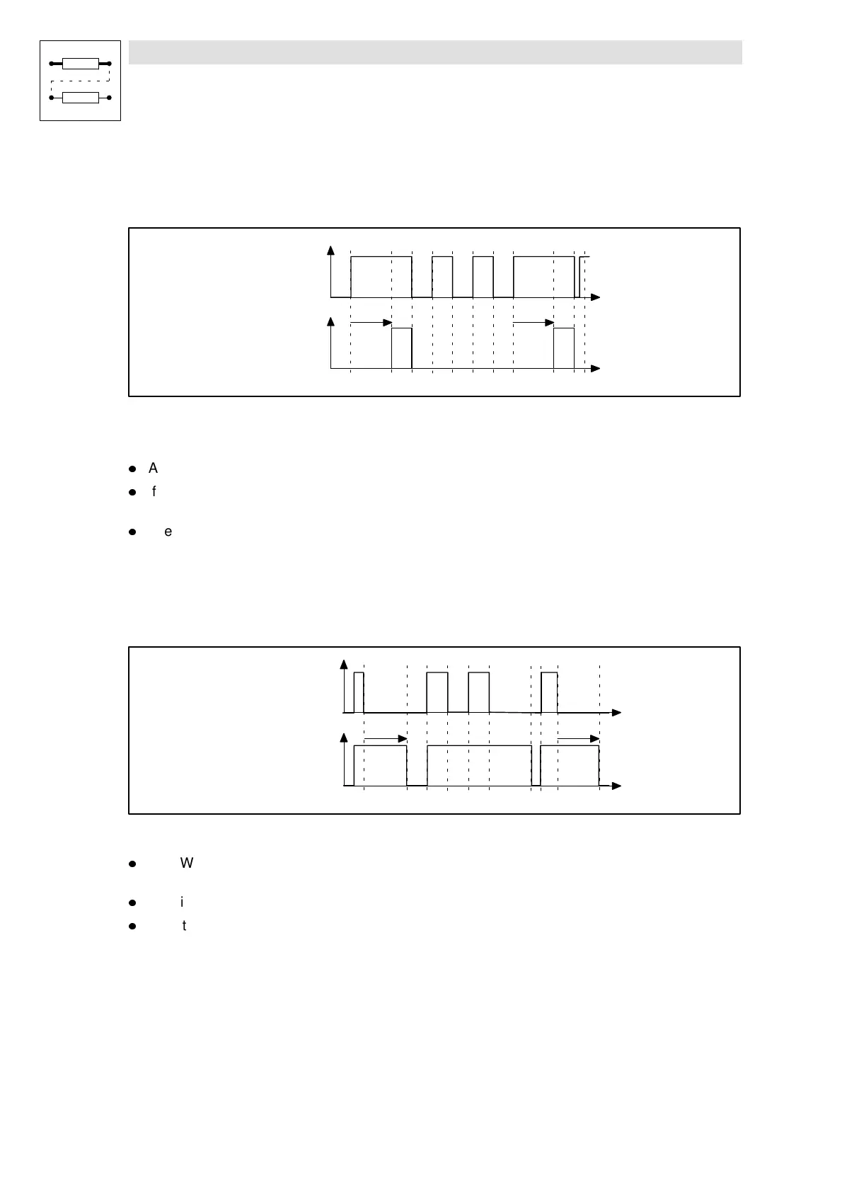
7.6.35.1 On-delay
If the on-delay is set, a signal change at the input DIGDELx-IN from LOW to HIGH is passed on to
the DIGDELx-OUT output after the delay time set under C0721 or C0726 has elapsed.
t
t
DIGDEL1-IN
DIGDEL1-OUT
C0721 C0721
Fig. 7-89 On-delay (DIGDEL1)
In this function, the time-element operates like a retriggerable monoflop:
l
A LOW-HIGH edge at the input DIGDELx-IN starts the time element.
l
If the delay time set under C0721 or C0726 has elapsed, the output DIGDELx-OUT is set to
HIGH.
l
The time element is reset and the output DIGDELx-OUT is set to LOW with a HIGH-LOW
edge at the input DIGDELx-IN.
7.6.35.2 Dropout delay
A dropout delay causes a signal change at the input DIGDELx-IN from HIGH to LOW to be passed
on to the output DIGDELx-OUT if the delay time set under C0721 or C0726 has elapsed.
t
t
DIGDEL1-IN
DIGDEL1-OUT
C0721 C0721
Fig. 7-90 Dropout delay (DIGDEL1)
l
A LOW-HIGH edge at the input DIGDELx-IN causes the output DIGDELx-OUT to be set to
HIGH and the time element to be reset.
l
The time element is started with a HIGH-LOW edge at the input DIGDELx-IN.
l
After the delay time set under C0721 or C0726 has elapsed, the output DIGDELx-OUT is set
to LOW.