Function block library
7-58
SHB9300CRV EN 2.0
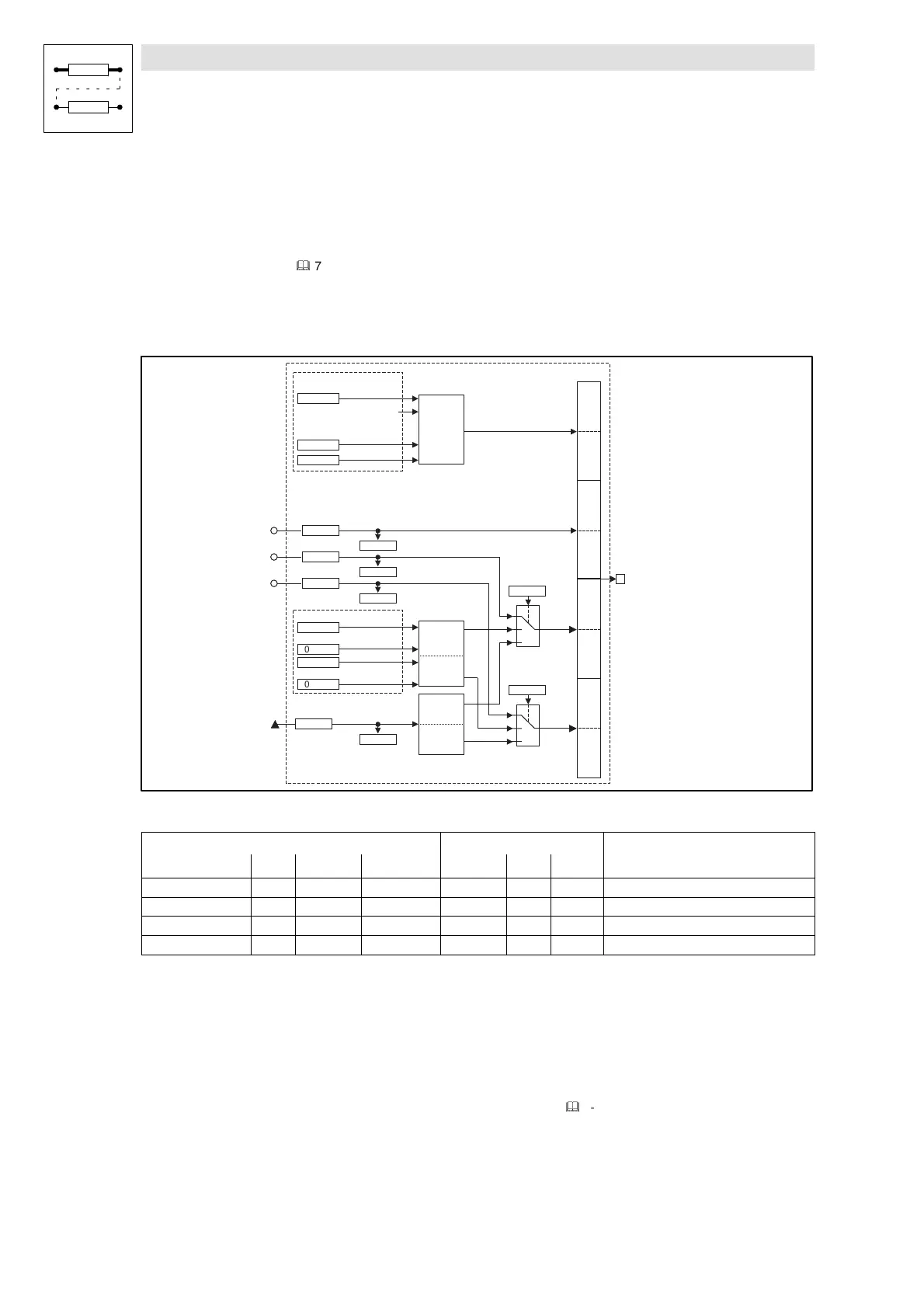
7.6.14 System bus (CAN-OUT)
Purpose
Interface for output signals from the system bus for setpoints and actual values as binary, analog,
or phase information.
(
&
7-51)
CAN-OUT1
The process data object CAN-OUT1 is provided for the cyclic transmission of process data and the
communication with a superimposed master.
CAN-OUT1
Status w ord
Bit 0
Bit 15
Bit 0
Bit 31
B y te 7 ,8
B y te 5 ,6
System bus
term inals
X4
B y te 3 ,4
1
0
2
C 0865/1
1
0
2
C 0864/1
CAN-OUT1.D1
16 Bit
Low W ord
16 Bit
H igh W ord
C 0861/1
16 Bit
Low W ord
16 Bit
H igh W ord
C 0869/1
FDO -0
CAN-OUT1.W 1
C 0860/1
C 0868/1
FDO -15
...
CAN-OUT1.W 2
C 0860/2
CAN-OUT1.W 3
C 0860/3
C 0868/2
C 0868/3
STAT.B0
DCTRL-IM P
...
STAT.B15
STAT.B14
16 Bit
FDO
C 0116/1
C 0116/16
FDO -16
FDO -31
...
C 0116/17
C 0116/32
Bit 0
Bit 15
C 0156/1
STAT
C 0156/6
C 0156/7
Fig. 7-47 System bus (CAN-OUT1)
Signal
Source Note
Name Type DIS DIS format CFG List Lenze
CAN-OUT1.W1 a C0868/1 dec [%] C0860/1 1 1000 +100 % = +16384
CAN-OUT1.W2 a C0868/2 dec [%] C0860/2 1 1000 +100 % = +16384
CAN-OUT1.W3 a C0868/3 dec [%] C0860/3 1 1000 +100 % = +16384
CAN-OUT1.D1 ph C0869/1 dec [inc] C0861/1 4 1000 1 revolution = 65536
Function
The input signals of this function block are copied to the 8 byte user data of CAN object 1 and laid
on the system bus. The meaning of the user data can be determined very easily with C0864/1 and
C0865/1 and the corresponding configuration code (CFG).
Byte 1 and 2
Here, the status word of the function block STAT is mapped.
(
&
7-214)
Some of the bits are freely assignable.
Byte 3 and 4
Here, the analog signal configured at the input CAN-OUT1.W1 is mapped.