EasyManua.ls Logo

Lenze EVS9326-EK User Manual

Lenze EVS9326-EK
524 pages
To Next Page IconTo Next Page
To Previous Page IconTo Previous Page
Page #244 background imageLoading...
Page #244 background image
Function block library
7-127

SHB9300CRV EN 2.0
7.6.39 Free piece counter (FCNT)
Purpose
Digital up/down counter.
FCNT1-CLKUP
C 1102/1
FCNT1-CLKDW N
C 1102/2
C 1104/1
C 1104/2
FCNT1-LD-VAL
C 1101/1
C 1103/1
FCNT1-LOAD
C 1102/3
C 1104/3
FCNT1-OUT
FCNT1-EQUAL
C 1101/2
C 1103/2
FCNT1-CM P-VAL
C 1100
CTRL
FCNT1
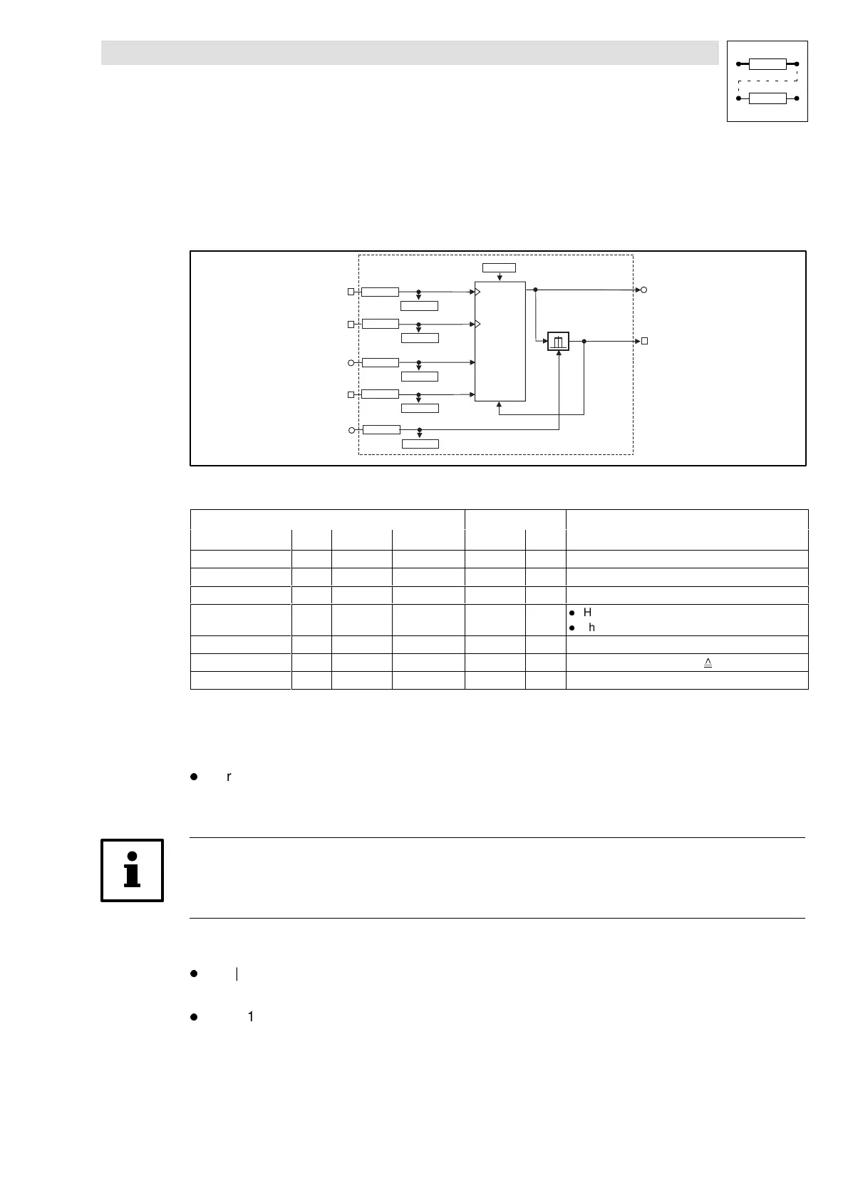
Fig. 7-96 Free piece counter (FCNT1)
Signal
Source Note
Name Type DIS DIS format CFG List
FCNT1-CLKUP d C1104/1 bin C1102/1 2 LOW-HIGH edge = counts up by 1
FCNT1-CLKDWN d C1104/2 bin C1102/2 2 LOW-HIGH edge = counts down by 1
FCNT1-LD-VAL a C1103/1 dec C1101/1 1 Start value
FCNT1-LOAD d C1104/3 bin C1102/3 2
l
HIGH = Accept start value
l
The input has the highest priority
FCNT1-CMP-VAL a C1103/2 dec C1101/2 1 Comparison value
FCNT1-OUT a - - - - Counter limited to ±199.99 % ( ±32767)
FCNT1-EQUAL d - - - - HIGH = comparison value reached
Function
C1100 = 1
l
For | counter |  | FCNT1-CMP-VAL | (comparison value):
– For 1 ms FCNT1-EQUAL = HIGH
– Resets the counter to the start value (FCNT1-LD-VAL)
Tip!
If thesignal isto beset for alonger time, e.g.when the output is requested by aPLC, you canextend
the signal with the TRANS function block.
C1100 = 2
l
For | counter | = | FCNT1-CMP-VAL | (comparison value):
– The counter stops
l
FCNT1-LOAD = HIGH resets the counter to the start value (FCNT1-LD-VAL)
Show/Hide Bookmarks

Table of Contents

Question and Answer IconNeed help?

Do you have a question about the Lenze EVS9326-EK and is the answer not in the manual?

Lenze EVS9326-EK Specifications

General IconGeneral
BrandLenze
ModelEVS9326-EK
CategoryDC Drives
LanguageEnglish

Summary

Safety information

Technical data

Rated data

Provides detailed electrical and mechanical specifications for various product types.

Fuses and cable cross-sections

Specifies recommended fuse types and cable cross-sections for mains and motor connections.

Installation

Mechanical installation

Covers important notes on mounting, ensuring free space, and possible mounting positions for the controller.

Electrical installation

Details protection of persons, controller, motor, mains types, and cable specifications.

Power connections

Explains preparations for power connections, including mains and motor connections.

Control connections

Outlines control cable specifications, terminal assignments, and connection diagrams.

Commissioning

Before switching on

Essential checks before initial switch-on, including wiring, power connections, and motor connection.

Parameter set generation

Systematic procedure for generating a parameter set by adapting controller to mains, motor, and machine parameters.

During operation

Configuration

Working with function blocks

Guides on configuring signal flow by connecting function blocks and understanding signal types.

Monitoring

Covers various monitoring functions that protect the drive from impermissible operating conditions and their reactions.

Parameter setting

Explains how to adapt the drive to applications by setting parameters via PC or keypad.

Troubleshooting and fault elimination

Troubleshooting

Explains how operational faults are indicated via display elements or status information and lists common causes.

Fault messages

Lists fault messages, their causes, and corresponding remedies for troubleshooting.

Signal flow charts

Related product manuals