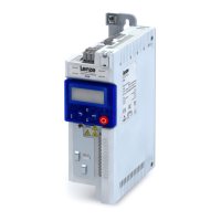
What to do if Lenze Inverter shows error pending with fault or trouble?
- BBrenda Wilson DDSJul 30, 2025
If a fault or trouble is indicated with an error pending on your Lenze Inverter, press the stop key to reset the error.

 Loading...
What to do if Lenze Inverter shows error pending with fault or trouble?
If a fault or trouble is indicated with an error pending on your Lenze Inverter, press the stop key to reset the error.
| Product Category | DC Drives |
|---|---|
| Series | i510 |
| Protection Class | IP20 |
| Communication | CANopen, Modbus RTU |
| Protection Features | Overvoltage, Undervoltage |
| Operating Temperature | -10 to +50 °C |
| Storage Temperature | -25 to +70 °C |
| Humidity | 5% to 95% (non-condensing) |
| Control Mode | V/f control |
Provides fundamental safety measures for workplace hazards and electrical safety.
Covers essential safety and connection requirements for electrical installation.
Provides a step-by-step guide for the inverter commissioning process.
Guides through the favorites menu for common parameters used in basic applications.
Explains V/f and SLVC motor control modes and their associated parameters.
Explains the inverter's operation modes and setpoint structure for control.
Covers diagnostic data, status words, and parameters for monitoring inverter performance.
Covers essential parameters for basic setup and configuration of the inverter.
Details the motor control modes, settings, and parameters for optimizing motor performance.
Covers configuration of digital and analog inputs/outputs and I/O functions.
Explains the PID controller setup for regulating speed based on process values.
Covers auxiliary functions like device management, keypad setup, DC brake, and energy management.
Provides a quick start guide for CANopen communication, including EDS registration and parameter setup.
Offers a quick start guide for Modbus communication, covering register mapping and control parameters.
Provides a quick start guide for Profibus communication, including node address and process data configuration.
Describes the CIA402 format, typically used for EtherCAT and CAN communication.
Provides a comprehensive list of error codes, fault types, and their descriptions.


