6 Function & parameter description
Group 4 – I/O setup
78 Lenze · Inverter i510 / i550 - Cabinet · Operation Manual · 0.4 EN · 02/2016
0: Not inverted
1: Inverted
Inversion of Digital Output 1
0: Not inverted
1: Inverted
Inversion of Digital Output 2
Note: Only with Application IO
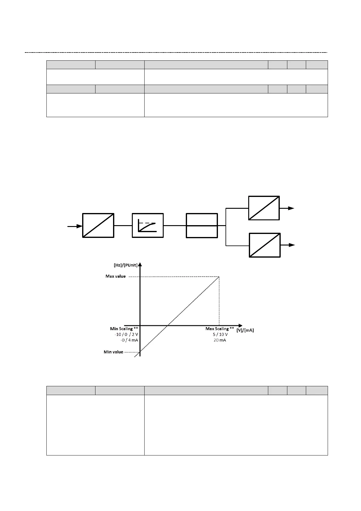
6.6.8 Analog input settings
The inverter is equipped with two analog inputs. These can be configured as reference or feedback singal.
The following settings are available:
Input configuration
Input filter time / Input Dead time
Input monitoring function
Input scaling
%
PUnit
%
Hz
Speed Scaling
V/I
%
Input Configuration
Filter
>?
<?
Monitoring
PID Scaling
** Availability of scaling depending on type of control unit.
0: 0...10VDC
1: 0...5VDC
2: 2...10VDC
3: -10...+10VDC (*)
4: 4...20mA
5: 0...20mA
Configuration of Analog input signal 1
Note: On i510 only current and unipolar voltage input available.

 Loading...


