6 Function & parameter description
Group 2 – Basic setup
Lenze · Inverter i510 / i550 - Cabinet · Operation Manual · 0.4 EN · 02/2016 51
6.4.3 Keypad setpoints
0.0 ... [20.0] ... 599.0 Hz
Actual Keypad setpoint, defined by Up and Down buttons
Process controller setpoint
-300.00 ... [0.00] ... 300.00 PUnit
Actual Keypad PID setpoint, defined by Up and Down buttons
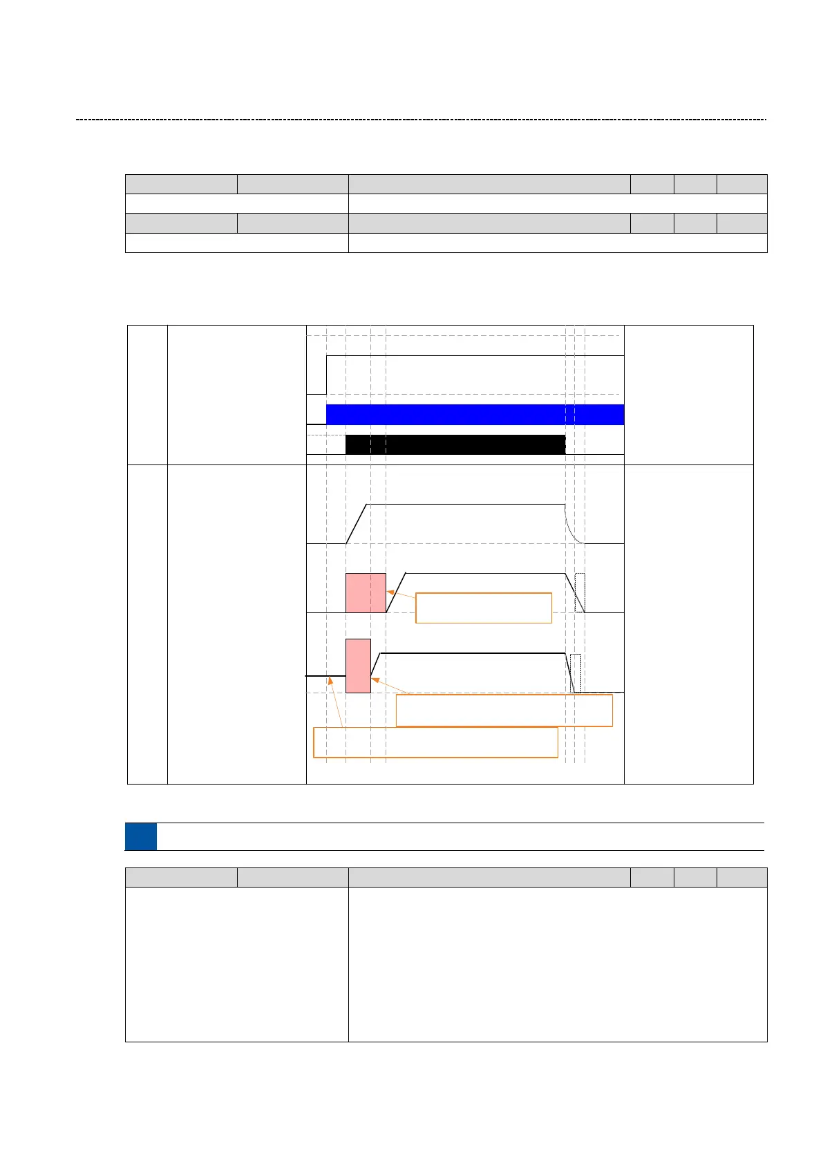
6.4.4 Start and Stop configuration
The motor can be started and stopped with different methods:
Frequency
Command
0 Hz
50 Hz
40 Hz
0 Hz
Input Signals /
Conditions
Output
TRUE
FALSE
Run/Stop command
40 Hz
Mains Power
P203:1=0
Normal
0 Hz
40 Hz
P203:1=1
Start with DC brake
DC
Brake
DC Brake is applied at the
time of Start / Run command.
0 Hz
40 Hz
P203:1=2
Flying Start
Some rotational speed may be present at time of
Start / Run command due to motor / load inertia
Speed
Detection
Motor speed sensing to catch a spinning
motor. Occurs on every Start / Run command.
Motor
Frequeny
Start method
Stop method
P203:3=0
Coast to Stop
P203:3=1
Standard Ramp
P203:3=2
Quick stop ramp
Motor
Frequeny
Motor
Frequeny
*
* The DC Brake can applied additionaly if required
*
Fig. 16: Start and Stop configuration
See chapter “6.9.3DC brake setup”, page 88 for DC brake setup
0: Normal
1: Start with DC brake
2: Flying Start
Defines starting method of the motor
0: Normal:
Inverter accelerates the motor in the selected direction when the start is
initiated
1: Start with DC brake:
Inverter apply the DC Brake when the start is initiated, before beginning
rotation of the motor. When the DC Brake delay time has elapsed the

 Loading...


