6 Function & parameter description
Group 7 – Auxiliary Functions
88 Lenze · Inverter i510 / i550 - Cabinet · Operation Manual · 0.4 EN · 02/2016
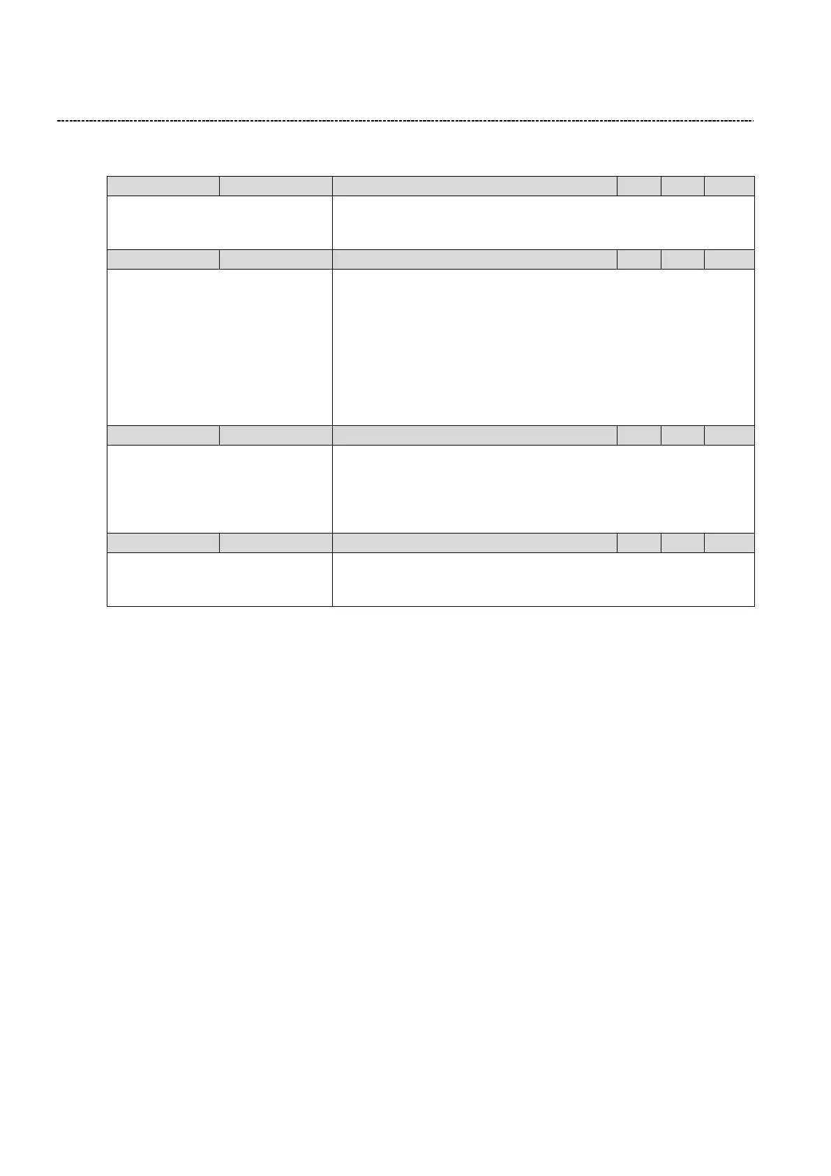
6.9.2 Keypad setup
Defines the setpoint increment by pressing UP/DOWN buttons on the
keypad.
(Scaling: Frequency = 0.1, PID = 0,01)
0.00 ... [0.00] ... 650.00
User unit can be shown on the keypad during running of hte motor. (Ex-
ample: Calculated speed after gearbox) The scaling factor P702:0 defines
the user unit:
User unit = "Actual frequency" x P702:0
The scaled user unit is also shown in P101:0 (0x400D:0)
Note:
0: Function disabled
In PID mode the user unit has to be selected setting P703:0 to the scaled
user unit (Set P703:0 = 0x400D0000)
0x0 ... [0x0] ... 0xFFFFFF00
The parameter which is show on the keypad during running of the motor
can be configured. Format: 0xiiiiss00 (iiii = Index heximal, ss=subindex)
Note:
0: Function disabled
Only parameters from group 1 can be selected.
Keypad language selection
0: No Language
1: English
2: German
Selects the language of the Keypad
6.9.3 DC brake setup
DC Braking creates a braking torque by injecting DC current into the motor. This is useful to aid in decelerating a
load that would otherwise take a long time due to inertia. It is also useful to lock the motor rotor either before
starting or upon stopping.
The DC-Brake can be used as follow:
1. Starting of the motor
DC-Brake can be selected as starting method in P203:1. At the starting of the motor the DC-Brake with the value
of P704:1 is applied for the time defined in P704:2. After that the speed is ramped up.
2. Stopping of the motor
If during stopping the motor frequency goes below the level P704:3 the inverter stops the speed deceleration
and applies the DC Brake with the value of P704:1 is applied for the time defined in P704:2.
3. Manually triggered (I.e. Digital IO)
The Trigger P400:5 activates the DC brake manually.
Note: The DC brake is ON as long as the function is triggered!

 Loading...


