EasyManua.ls Logo

Lenze i510 User Manual

Lenze i510
127 pages
To Next Page IconTo Next Page
To Previous Page IconTo Previous Page
Page #23 background imageLoading...
Page #23 background image
5 Commissioning
Set-up tools
Lenze · Inverter i510 / i550 - Cabinet · Operation Manual · 0.4 EN · 02/2016 23
5.1.2 Keypad
The keypad with display is snapped on the front side of the inverter.
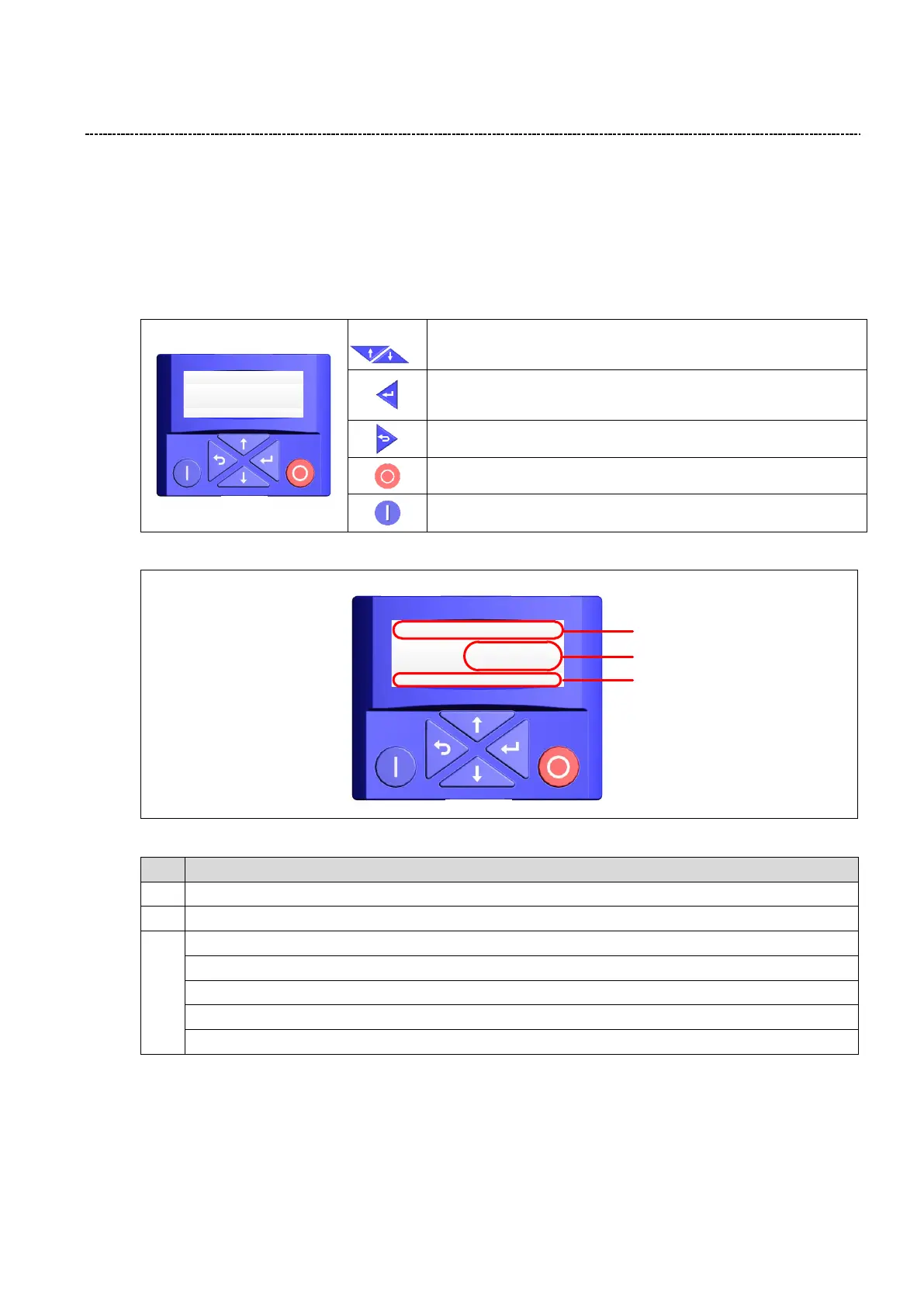
Keypad (Type code: i5MADK0000000S)
Operating elements
Navigation in menu
Adjust parameter values
Enter (sub-)menu/parameter
Confirm parameter
Exit (sub-)menu/parameter
Keystop inverter
Enable inverter
Display
Fig. 9: Keypad display
Pos.
Description
1
Status and unit
2
Speed / Parameter value / Fault code
3
LOC • Local start button on keypad is active (stop button is always active)
REM • Local start button is inactive (start is initiated remotely)
MAN • Up/Down arrows are active and control speed
AUTO • Up/Down arrows are inactive (speed control is external)
Set • When blinking indicates that a setting or value has changed and needs to be entered
REM AUTO
AI1 config
SET
P430.01
LOC REM MAN AUTO
Vel:Run:FWD Hz
SET
20 .0
1
2
3

Table of Contents

Other manuals for Lenze i510

Questions and Answers:

Lenze i510 Specifications

General IconGeneral
Product CategoryDC Drives
Seriesi510
Protection ClassIP20
CommunicationCANopen, Modbus RTU
Protection FeaturesOvervoltage, Undervoltage
Operating Temperature-10 to +50 °C
Storage Temperature-25 to +70 °C
Humidity5% to 95% (non-condensing)
Control ModeV/f control

Summary

Safety Information

Basic Safety Measures

Provides fundamental safety measures for workplace hazards and electrical safety.

Installation

Electrical Installation

Covers essential safety and connection requirements for electrical installation.

Commissioning

Commissioning Procedure

Provides a step-by-step guide for the inverter commissioning process.

Parameter Setup via Favorites

Guides through the favorites menu for common parameters used in basic applications.

Motor Control Modes

Explains V/f and SLVC motor control modes and their associated parameters.

Function and Parameter Description

Control Concept

Explains the inverter's operation modes and setpoint structure for control.

Diagnostics Group (Group 1)

Covers diagnostic data, status words, and parameters for monitoring inverter performance.

Basic Setup Group (Group 2)

Covers essential parameters for basic setup and configuration of the inverter.

Motor Control Group (Group 3)

Details the motor control modes, settings, and parameters for optimizing motor performance.

I/O Setup Group (Group 4)

Covers configuration of digital and analog inputs/outputs and I/O functions.

PID Setup Group (Group 6)

Explains the PID controller setup for regulating speed based on process values.

Auxiliary Functions Group (Group 7)

Covers auxiliary functions like device management, keypad setup, DC brake, and energy management.

Fieldbus Communication

CANopen Quick Start

Provides a quick start guide for CANopen communication, including EDS registration and parameter setup.

Modbus Quick Start

Offers a quick start guide for Modbus communication, covering register mapping and control parameters.

Profibus Quick Start

Provides a quick start guide for Profibus communication, including node address and process data configuration.

Drive Profiles and Fieldbus

CIA402 Drive Profile

Describes the CIA402 format, typically used for EtherCAT and CAN communication.

Troubleshooting

Error Messages List

Provides a comprehensive list of error codes, fault types, and their descriptions.

Related product manuals